LH-Jetronic Circuit Operation
COMMON CONDITIONS.As soon as the ignition is switched ON, voltage is also fed to terminal 20 of the Electronic Control Unit (ECU). This voltage energizes the various circuits of the ECU.
When the ignition switch energizes the starter motor, a signal is also sent to terminal 4 of the ECU.
Signals that the engine is rotating are fed from the ignition system to terminal 1 of the ECU. These signals will cause energizing of system relay (G) and fuel pump relay (T) and thereby also energize terminal 10 of the ECU.
The air mass meter (K) measures the inducted air mass and provides an input signal to terminal 7 of the ECU.
Under all conditions, the temperature sensor (L) senses coolant temperature and sends corresponding signal to the ECU terminal 13.
STARTING ENGINE COLD.
The thermal time switch (M) provides a ground for the cold start injector for cold start enrichment.
The thermal time switch (M) reduces cold start injector (P) operating time as coolant temperature rises.
Injection terminates completely at 15°C (59°F).
Vacuum switch (B) normally grounds terminal 3 of the ECU.
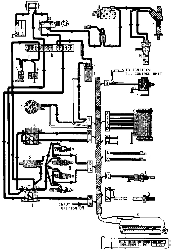
LEGEND:
A Fuel tank pump
B Vacuum switch
C Tachometer
D Fuse box
E Capacitor, tank pump
F Connector, tank pump
G System relay
H Starter motor
I Ignition coil
J Test pick-up connectors
K Air mass meter
L Temperature sensor
M Thermal time switch
N Injectors (four)
O Oxygen sensor
P Cold start injector
R Connector, Electronic Control Unit
S Fuel pump (main pump)
T Fuel pump relay
STARTING ENGINE WARM.
Vacuum switch (B) normally grounds terminal 3 of the ECU.
The ECU receives input signals from the various sensors. Soon after start, the oxygen sensor (0) is heated up by the exhaust gases and starts to signal the ECU.
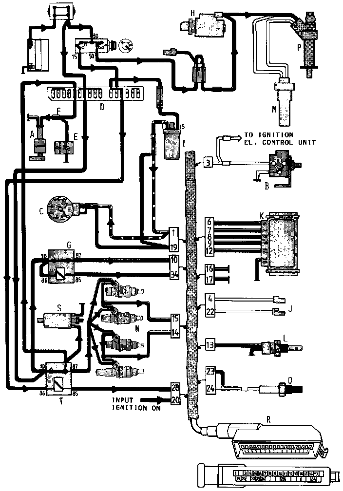
LEGEND:
A Fuel tank pump
B Vacuum switch
C Tachometer
D Fuse box
E Capacitor, tank pump
F Connector, tank pump
G System relay
H Starter motor
I Ignition coil
J Test pick-up connectors
K Air mass meter
L Temperature sensor
M Thermal time switch
N Injectors (four)
O Oxygen sensor
P Cold start injector
R Connector, Electronic Control Unit
S Fuel pump (main pump)
T Fuel pump relay
ENGINE RUNNING.
Various signals are received and processed by the Electronic Control Unit:
The air mass meter (K) measures the inducted air mass.
The temperature sensor (L) senses coolant temperature.
Terminal 1 receives an engine speed signal from the ignition coil.
The oxygen sensor (0) checks the exhaust gas contents.
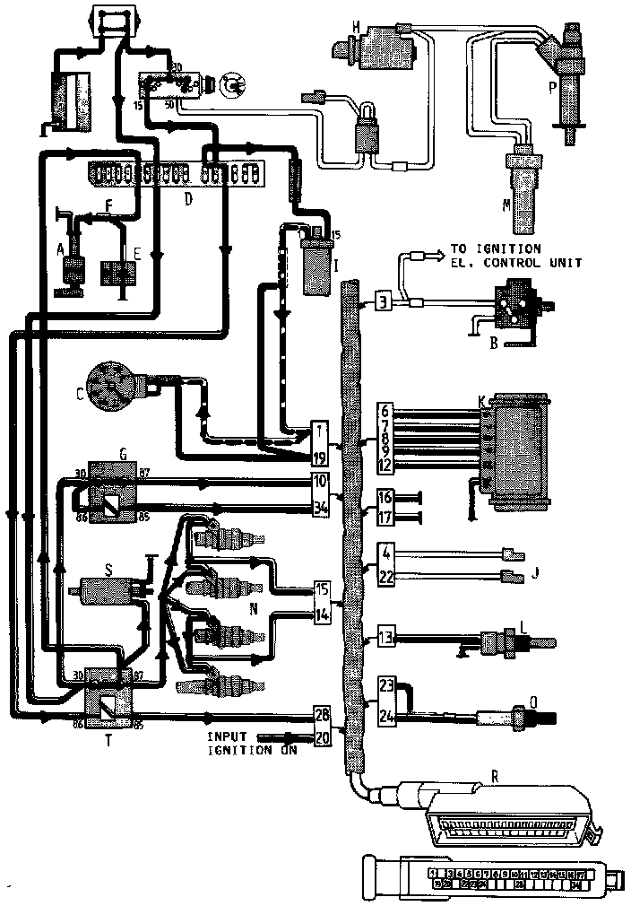
LEGEND:
A Fuel tank pump
B Vacuum switch
C Tachometer
D Fuse box
E Capacitor, tank pump
F Connector, tank pump
G System relay
H Starter motor
I Ignition coil
J Test pick-up connectors
K Air mass meter
L Temperature sensor
M Thermal time switch
N Injectors (four)
O Oxygen sensor
P Cold start injector
R Connector, Electronic Control Unit
S Fuel pump (main pump)
T Fuel pump relay
ENGINE STALLED.
Ignition ON but engine not running. Engine at normal operating temperature. There are no speed signals from the ignition coil, so the control ground circuit for the fuel pump relay (T) and system relay (G) is opened. The system becomes inactive and the fuel pumps stop.
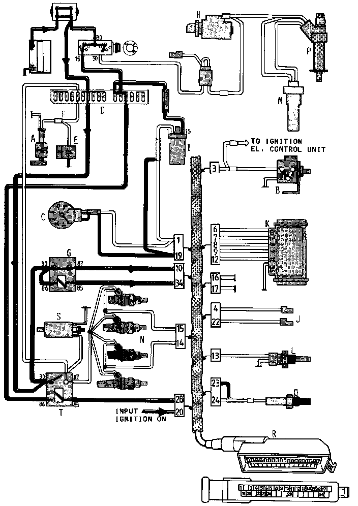
LEGEND:
A Fuel tank pump
B Vacuum switch
C Tachometer
D Fuse box
E Capacitor, tank pump
F Connector, tank pump
G System relay
H Starter motor
I Ignition coil
J Test pick-up connectors
K Air mass meter
L Temperature sensor
M Thermal time switch
N Injectors (four)
O Oxygen sensor
P Cold start injector
R Connector, Electronic Control Unit
S Fuel pump (main pump)
T Fuel pump relay