Ignition and System Repairing
Ignition system
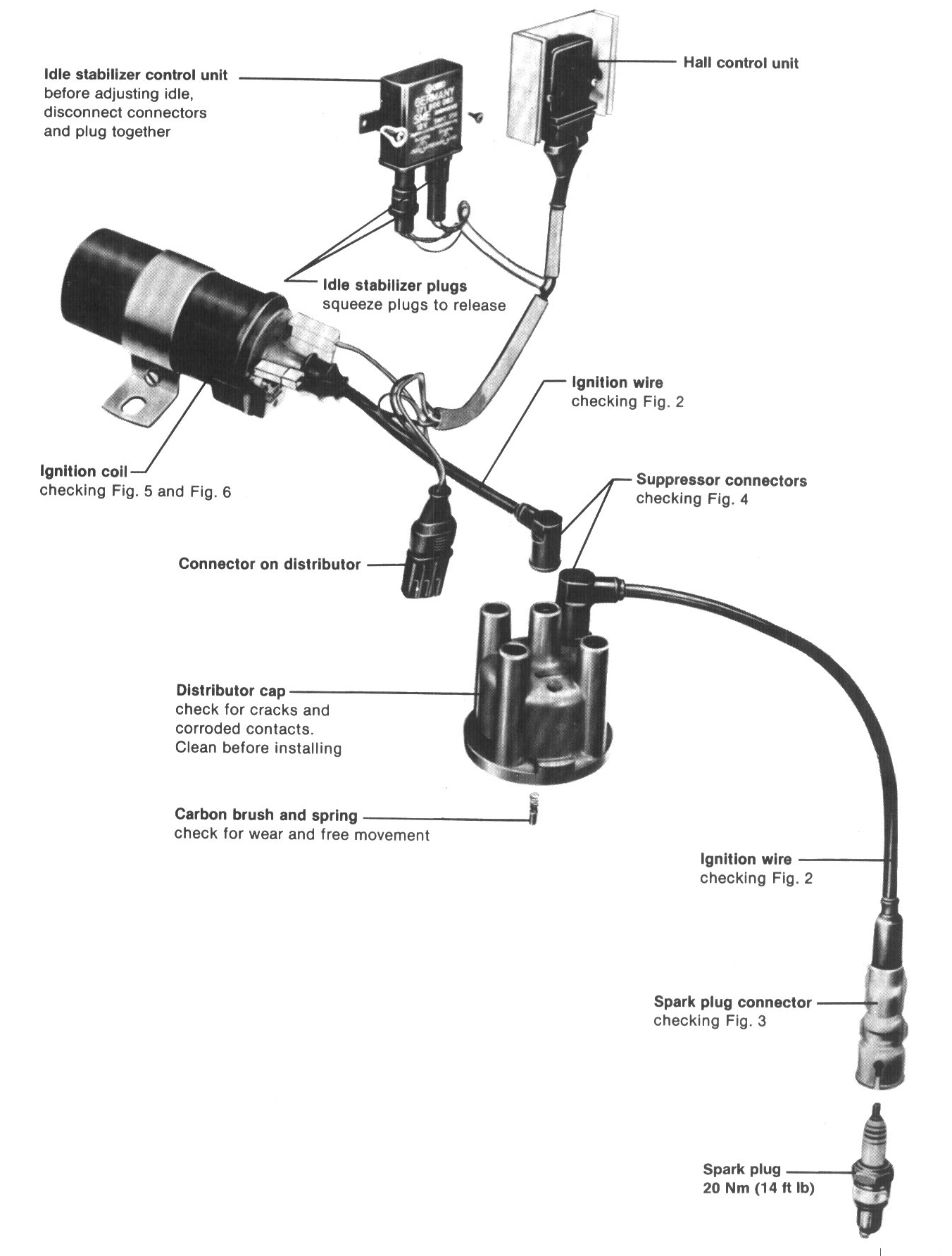
Ignition distributor and settings
CAUTION: When working on vehicles with Hall ignition system, observe following precautions to prevent injury or damage to ignition system:
- Do not touch or remove high tension wire when running or cranking engine
- Disconnect ignition wires only when ignition is switched off
- Test instruments should be connected/disconnected only when ignition is switched off
- Do not connect any condenser to terminal 1
- Do not tow cars without disconnecting plugs on ignition control unit
- Do not crank engine until high tension wire of distributor cap (terminal 4) is connected to ground with jumper wire (example: compression check, etc.)
- Do not leave battery connected when electric welding on car
- Do not substitute rotor of ignition distributor with one of different type
- When installing suppressor, use only 1000 ohms for high tension wires and 1000 to 5000 ohms for spark plug connectors
- Do not wash engine when it is running
- Do not use battery booster longer than 1 minute nor exceed 16.5 volts with booster
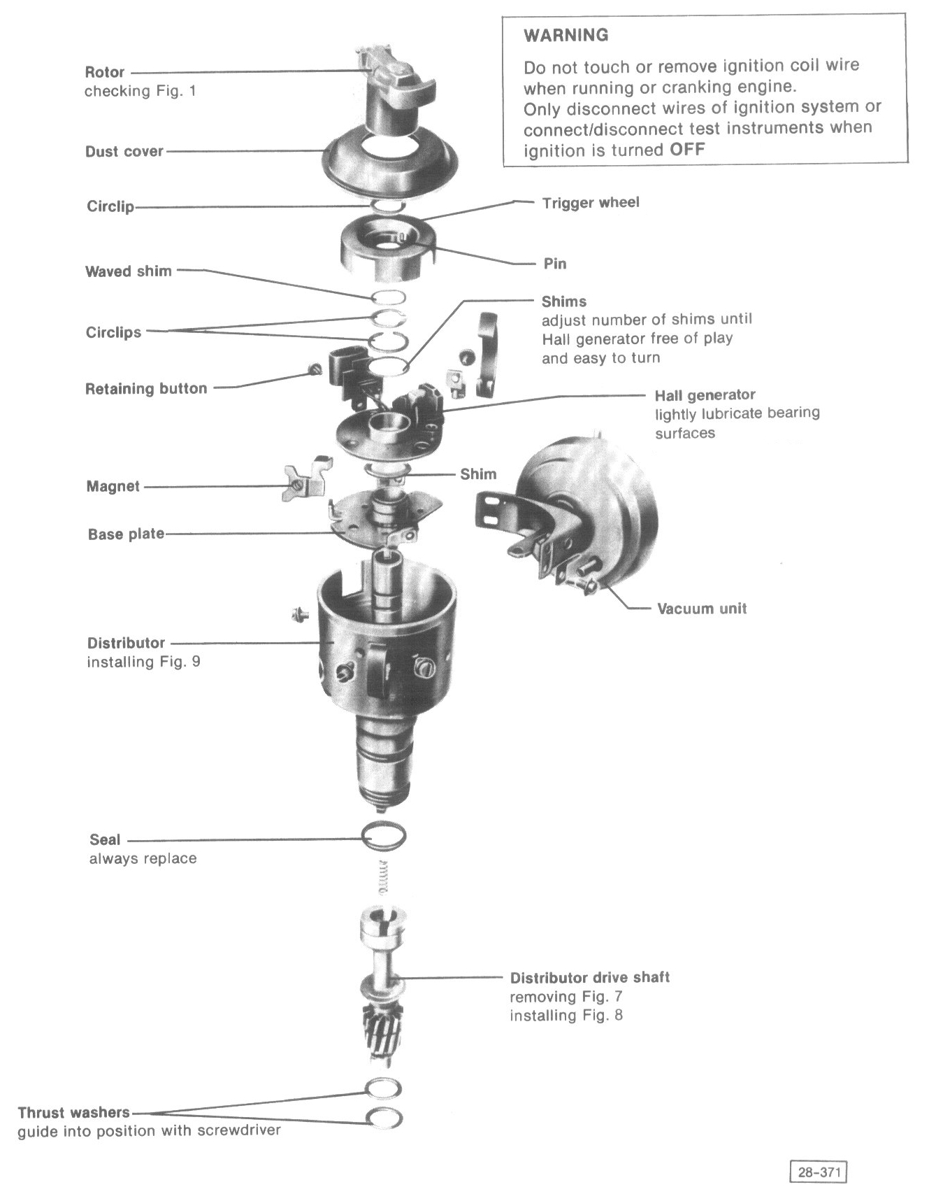
Fig. 1 Rotor, checking

- Check that resistance is 1000 ±400 ohms
Note: Rotor must be marked with R1 for Hall generator equipped cars
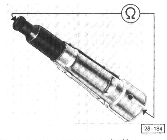
Fig. 2 Ignition wires and connectors, checking
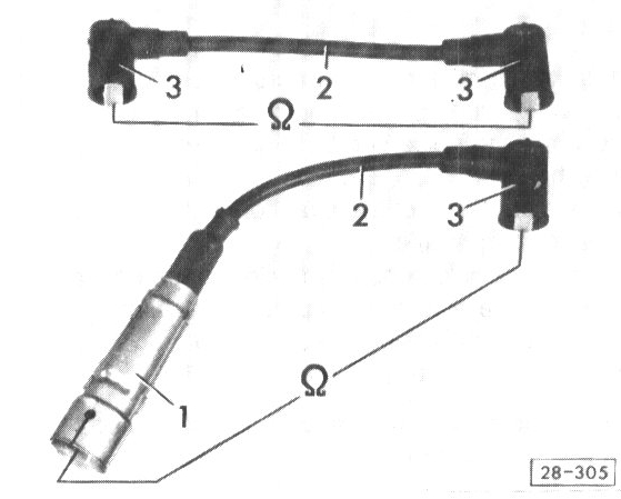
- Check wire 2 between ignition coil and distributor (including connectors 3)
Resistance should be = 2000 ±800 ohms
- Check wires 2 between distributor and spark plugs (including connectors 3and 1)
Resistance should be = 6000 ±1400 ohms
- If values are not as specified, check wires and connectors individually
Resistance of wires (without connectors) must be = 0 ohms
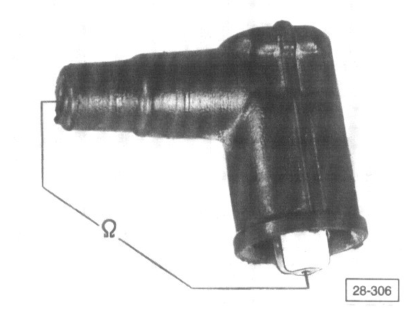
Fig. 3 Spark plug connectors, checking
- Check connectors resistance specified value = 5000 ±1000 ohms
Note: A rough idle or misfire during partial load could be caused by ignition sparks jumping from the plug wire connector to the noise suppression shield, or the cylinder head.
- Remove and inspect the plug connector for white spots or burn marks
- On those vehicles equipped with a suppressor shield on the distributor cap, it is necessary to remove the shield and check for white spots or burn marks on the distributor cap
If white spots or burn marks are present, replace the damaged components.
Fig. 4 Suppressor connectors, checking
- Check resistance of suppressor connectors
Specified value = 1000 ±400 ohms
Fig. 5 Ignition coil primary resistance, checking
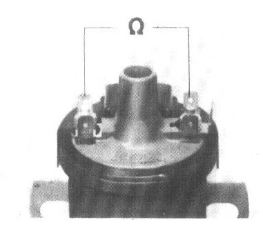
Note: If traces of leakage from ignition coil are visible check HALL control unit and replace ignition coil
- Disconnect all wires from coil terminals
- Connect ohmmeter between terminal 1 (-) and terminal 15 (+)
Resistance should be = 0.420 - 0.760 ohms
- Check secondary resistance (Fig. 6)
Fig. 6 Ignition coil secondary resistance, checking
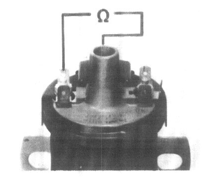
- connect ohmmeter between terminal 1 (-) and terminal 4
Resistance should be = 2400 - 3500 ohms
If NO, replace ignition coil
Note: If resistance readings are correct, but no high voltage occurs at ignition coil, check Hall generator and Hall control unit. If necessary, replace ignition coil.
Fig. 7 Distributor drive shaft, removing
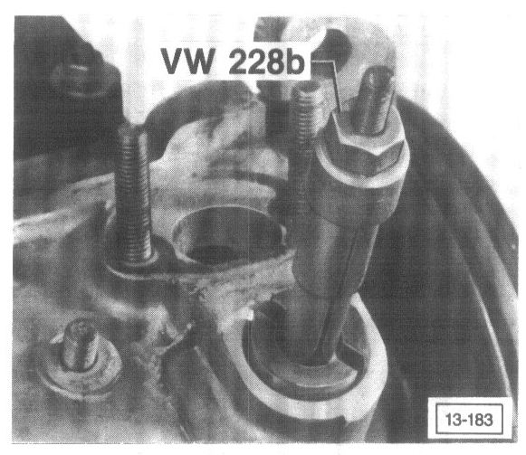
- Use extractor with diameter 14.8 - 18.5 mm (0.583 - 0.728 in)
Fig. 8 Distributor drive shaft, installing
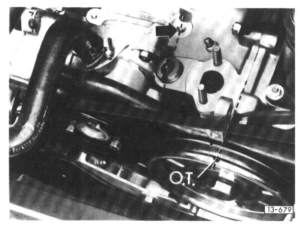
- Set crankshaft to TDC on No.1 cylinder
- Insert drive shaft so that offset slot in top of drive shaft is pointing toward tapped hole (arrow)
Smaller segment points to water pump
Fig. 9 Distributor, installing
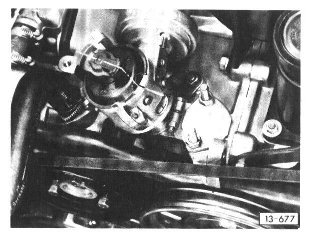
- Set crankshaft to TDC on cylinder No.1
- Turn rotor until it is pointing to No.1 cylinder mark on edge of housing
- Install distributor
- Clean distributor cap, check for cracks, signs of tracking and rotor tightness on shaft
- Adjust ignition timing