Part 2
NETWORKING: CAN COMMUNICATION SYSTEM: TERMINALS OF ECU (Continued..)
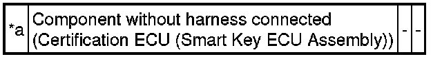
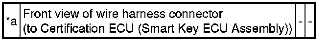
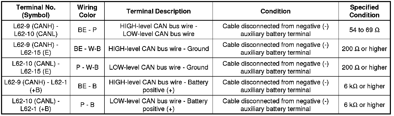
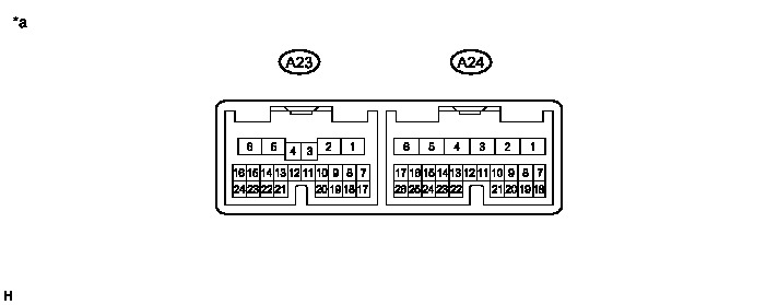
16. CERTIFICATION ECU (SMART KEY ECU ASSEMBLY)
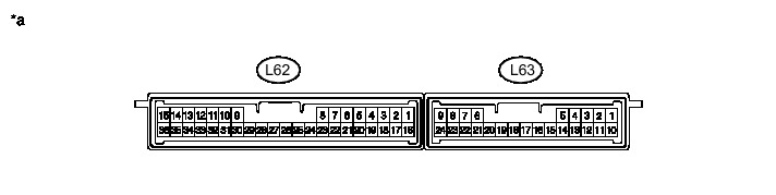
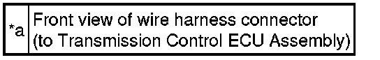
Text in Illustration
(a) Disconnect the cable from the negative (-) auxiliary battery terminal.
(b) Disconnect the certification ECU (smart key ECU assembly) connector.
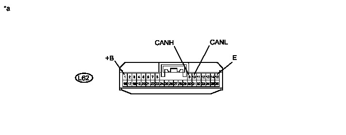
Text in Illustration
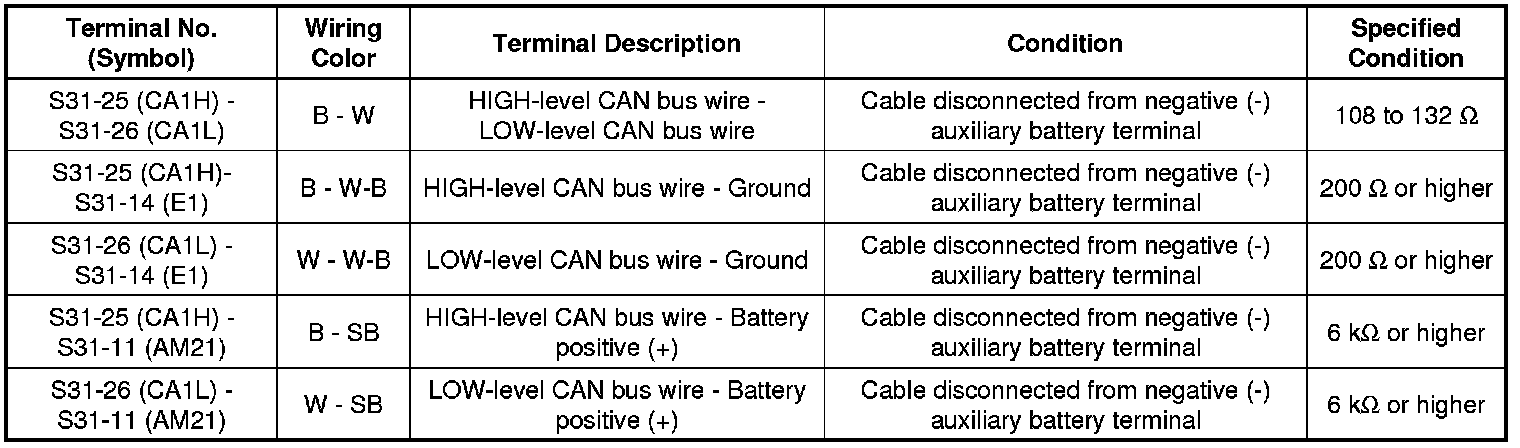
(c) Measure the resistance according to the value(s) in the table below.
Standard Resistance:
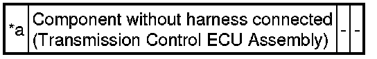
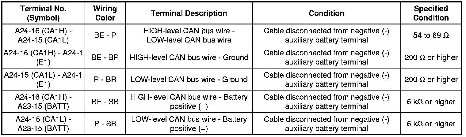
17. TRANSMISSION CONTROL ECU ASSEMBLY
Text in Illustration
(a) Disconnect the cable from the negative (-) auxiliary battery terminal.
(b) Disconnect the transmission control ECU assembly connectors.
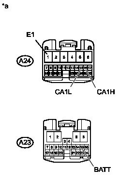
Text in Illustration
(c) Measure the resistance according to the value(s) in the table below.
Standard Resistance:
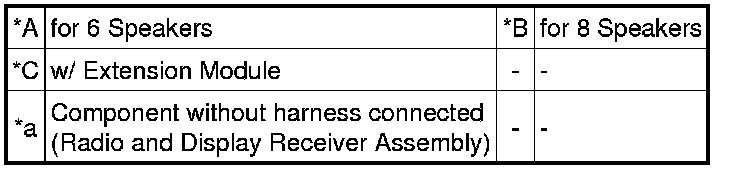
18. RADIO AND DISPLAY RECEIVER ASSEMBLY (for Radio and Display Type)
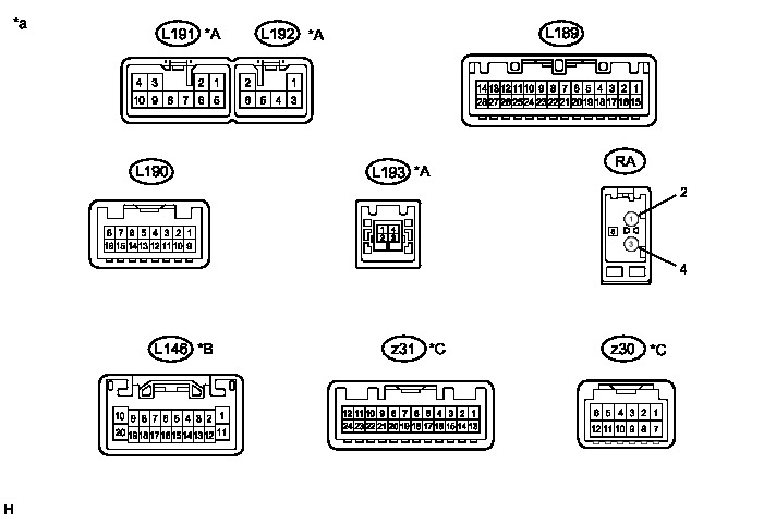
Text in Illustration
(a) Disconnect the cable from the negative (-) auxiliary battery terminal.
(b) Disconnect the radio and display receiver assembly connectors.
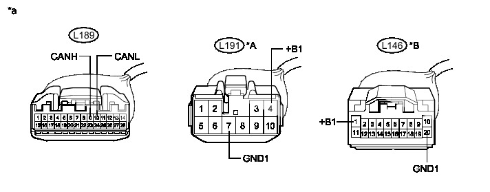
Text in Illustration
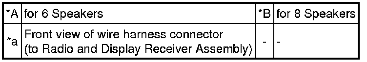
(1) Measure the resistance according to the value(s) in the table below.
Standard Resistance:
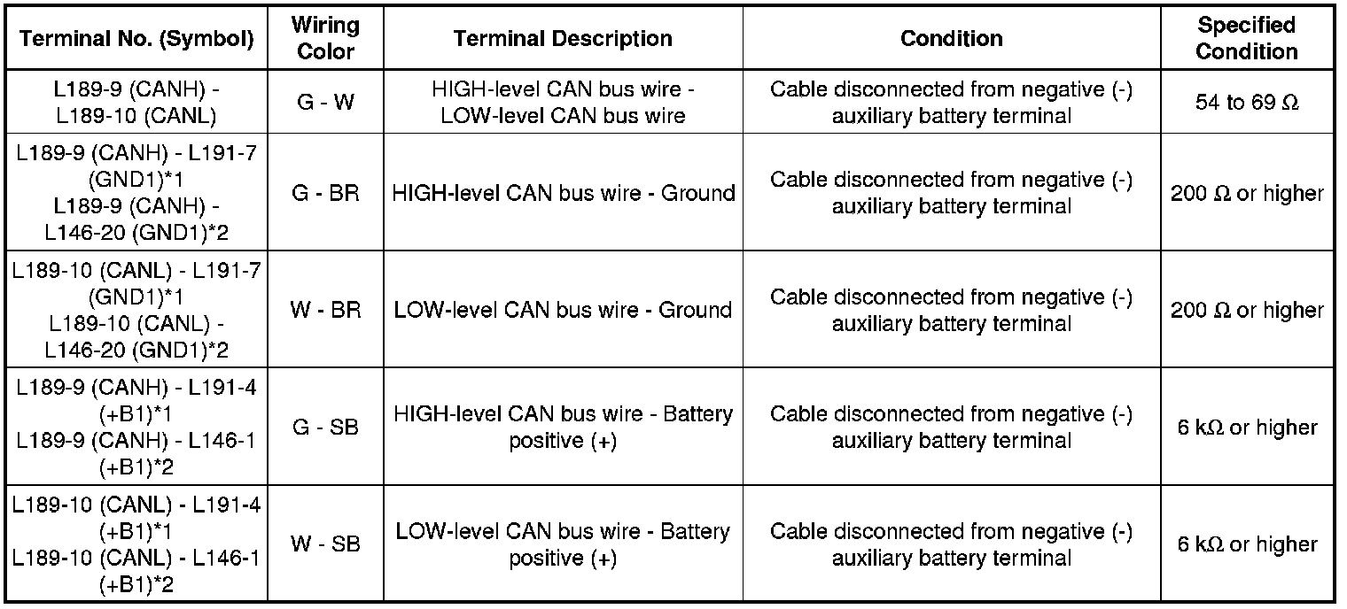
*1: for 6 speakers
*2: for 8 speakers
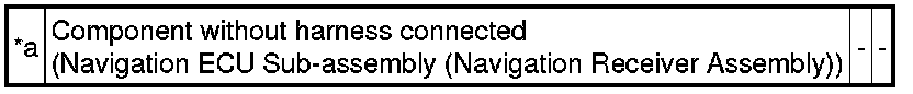
19. NAVIGATION ECU SUB-ASSEMBLY (NAVIGATION RECEIVER ASSEMBLY) (for Navigation Receiver Type)
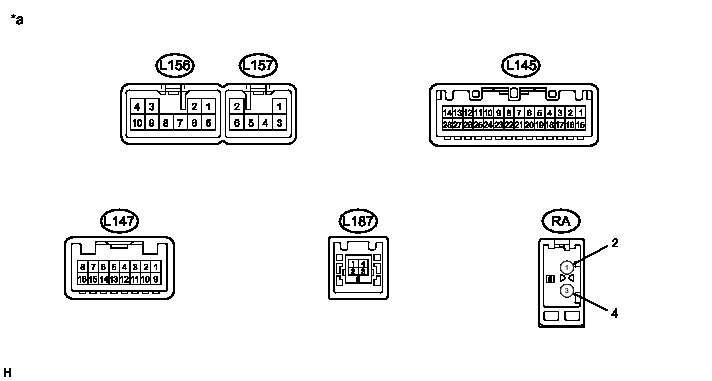
Text in Illustration
(a) Disconnect the cable from the negative (-) auxiliary battery terminal.
(b) Disconnect the navigation ECU sub-assembly (navigation receiver assembly) connectors.
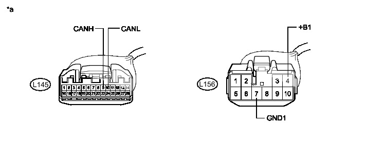
Text in Illustration

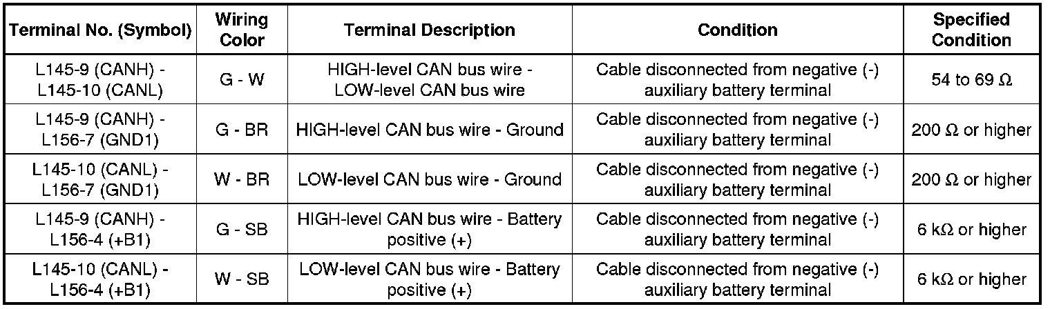
(1) Measure the resistance according to the value(s) in the table below.
Standard Resistance:
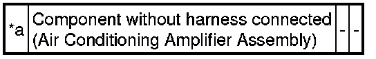
20. AIR CONDITIONING AMPLIFIER ASSEMBLY
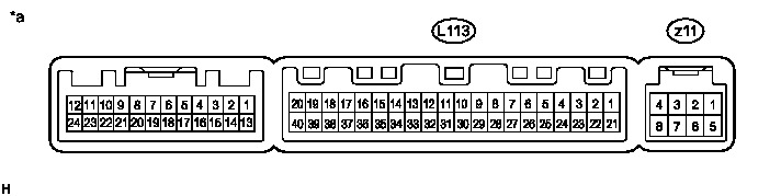
Text in Illustration
(a) Disconnect the cable from the negative (-) auxiliary battery terminal.
(b) Disconnect the air conditioning amplifier assembly connector.
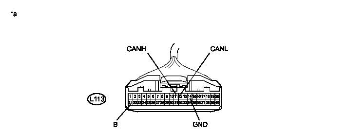
Text in Illustration
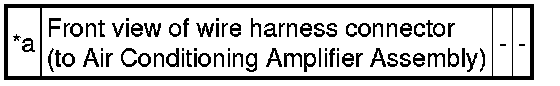
(c) Measure the resistance according to the value(s) in the table below.
Standard Resistance:
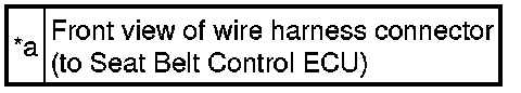
21. SEAT BELT CONTROL ECU (w/ Pre-collision System)
Text in Illustration
(a) Disconnect the cable from the negative (-) auxiliary battery terminal.
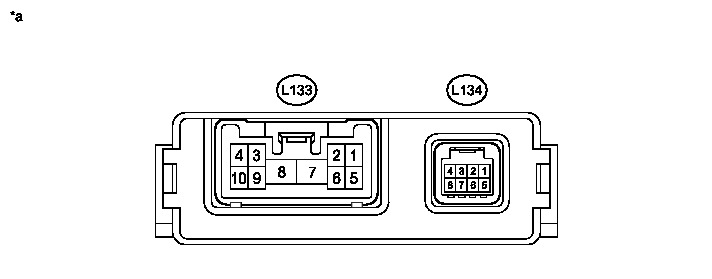
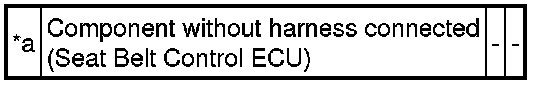
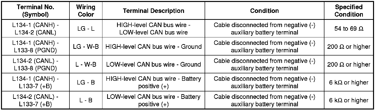
(b) Disconnect the seat belt control ECU connectors.
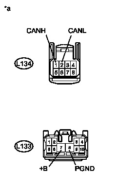
Text in Illustration
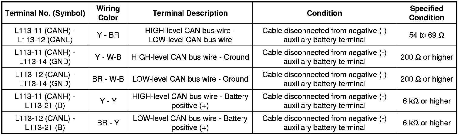
(c) Measure the resistance according to the value(s) in the table below.
Standard Resistance:
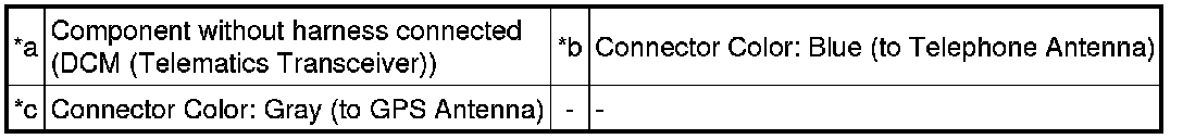
22. DCM (TELEMATICS TRANSCEIVER) (w/ Manual (SOS) Switch)
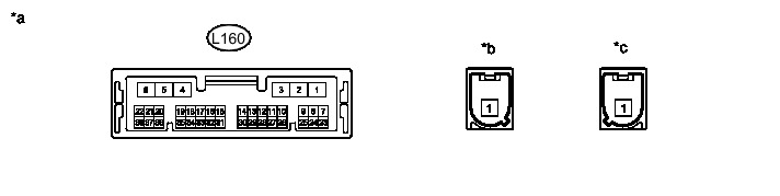
Text in Illustration
(a) Disconnect the cable from the negative (-) auxiliary battery terminal.
(b) Disconnect the DCM (telematics transceiver) connector.
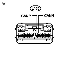
Text in Illustration
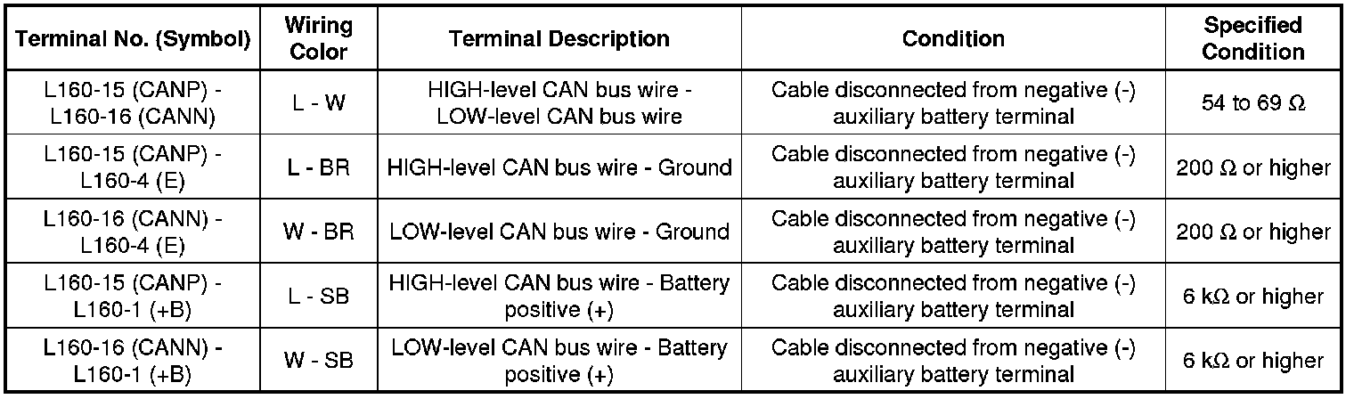
(c) Measure the resistance according to the value(s) in the table below.
Standard Resistance:
23. DRIVING SUPPORT ECU (w/ Dynamic Radar Cruise Control System)
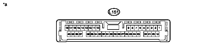
Text in Illustration
(a) Disconnect the cable from the negative (-) auxiliary battery terminal.
(b) Disconnect the driving support ECU connector.
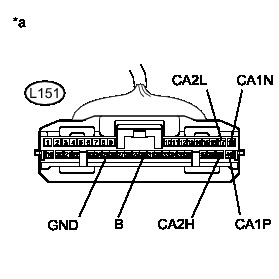
Text in Illustration
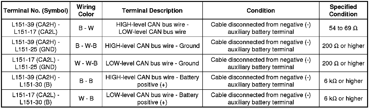
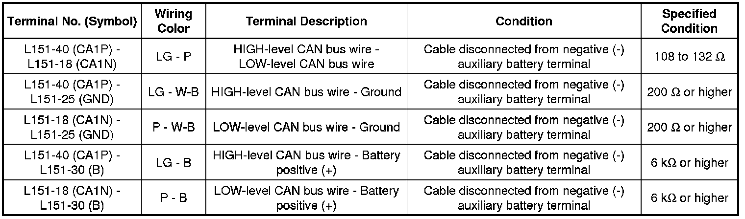
(c) Measure the resistance according to the value(s) in the table below.
Standard Resistance:
V2 Bus Branch Wire
Standard Resistance:
Parking Assist Bus Main Wire
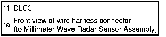
24. MILLIMETER WAVE RADAR SENSOR ASSEMBLY (w/ Dynamic Radar Cruise Control System)
(a) Disconnect the cable from the negative (-) auxiliary battery terminal.
(b) Disconnect the millimeter wave radar sensor assembly connector.
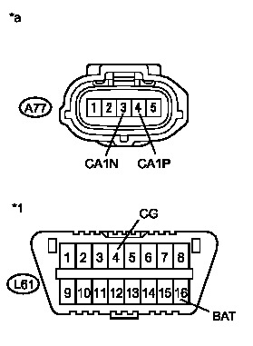
Text in Illustration
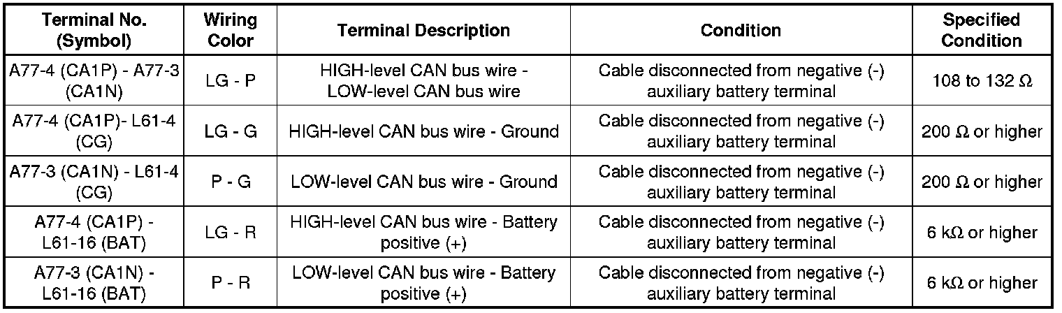
(c) Measure the resistance according to the value(s) in the table below.
Standard Resistance:
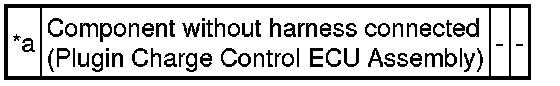
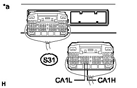
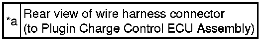
25. PLUG-IN CHARGE CONTROL ECU ASSEMBLY
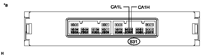
Text in Illustration
(a) Disconnect the cable from the negative (-) auxiliary battery terminal.
(b) Disconnect the plug-in charge control ECU assembly connector.
Text in Illustration
(c) Measure the resistance according to the value(s) in the table below.
Standard Resistance: