Part 1
CAN COMMUNICATION: CAN COMMUNICATION SYSTEM: Check CAN Bus Line for Short to +B
- Check CAN Bus Line for Short to +B
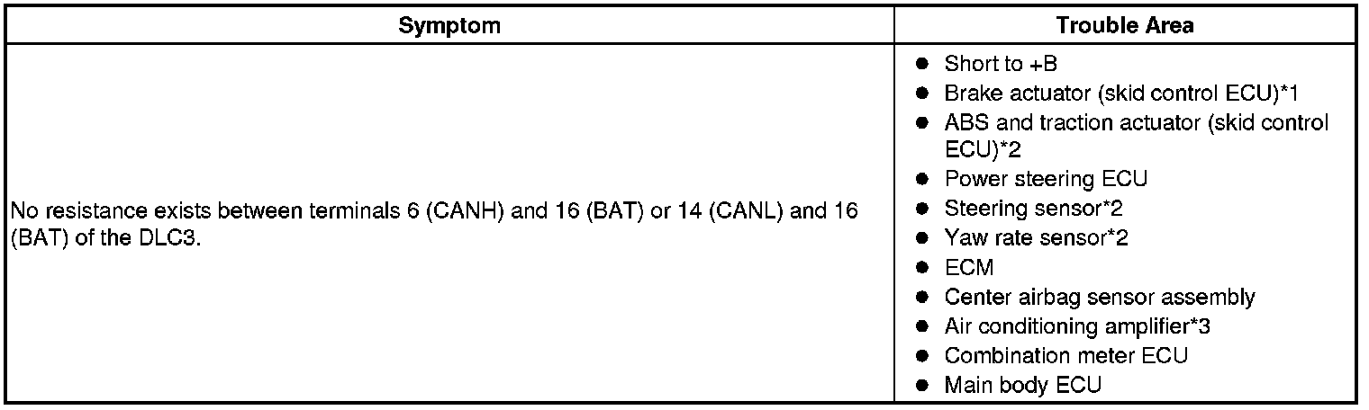
DESCRIPTION
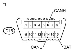
There may be a short circuit between the CAN bus line and +B when no resistance exists between terminals 6 (CANH) and 16 (BAT) or terminals 14 (CANL) and 16 (BAT) of the DLC3.
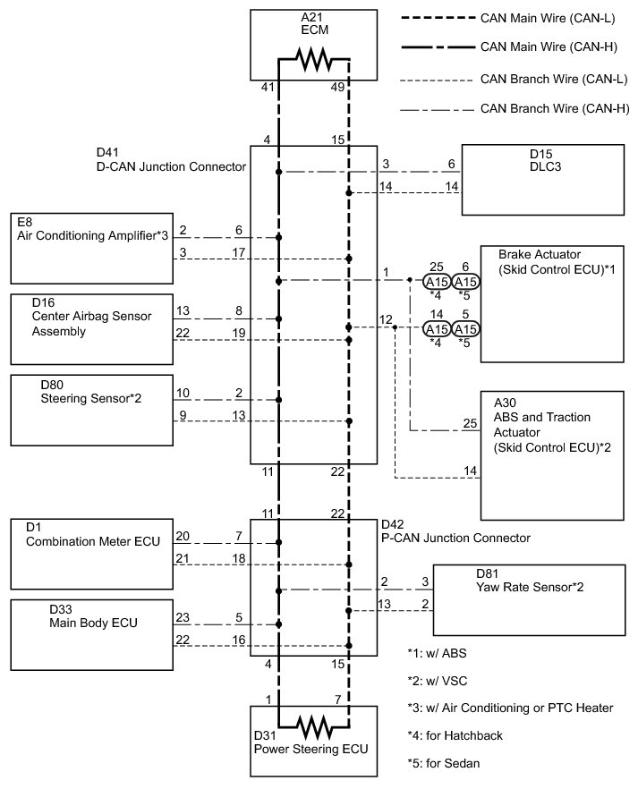
* *1: w/ ABS
* *2: w/ VSC
* *3: w/ air conditioning or PTC heater
WIRING DIAGRAM
INSPECTION PROCEDURE
NOTICE:
* Turn the ignition switch off before measuring the resistances of the CAN main wire and the CAN branch wire.
* After the ignition switch is turned off, check that the key reminder warning system and light reminder warning system are not in operation.
* Before measuring the resistance, leave the vehicle as is for at least 1 minute and do not operate the ignition switch, any other switches or the doors. If doors need to be opened in order to check connectors, open the doors and leave them open.
HINT
Operating the ignition switch, any switches or any doors triggers related ECU and sensor communication with the CAN, which causes resistance variation.
PROCEDURE
1. CHECK CAN BUS LINE FOR SHORT TO +B (DLC3 BRANCH WIRE)
(a) Turn the ignition switch off.

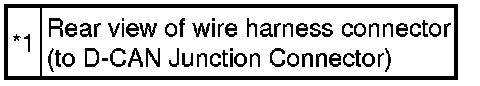
(b) Disconnect the D41 D-CAN junction connector.
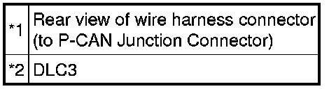
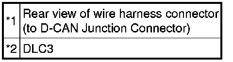
Text in Illustration
(c) Measure the resistance according to the value(s) in the table below.
Standard Resistance:

Text in Illustration
NG -- REPAIR OR REPLACE CAN BRANCH WIRE CONNECTED TO DLC3 (CAN-H, CAN-L)
OK -- Continue to next step.
2. CONNECT CONNECTOR
(a) Reconnect the D-CAN junction connector.
NEXT -- Continue to next step.
3. CHECK CAN BUS LINE FOR SHORT TO +B (P-CAN J/C SIDE)
(a) Turn the ignition switch off.
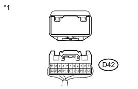
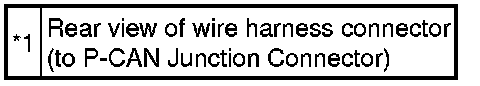
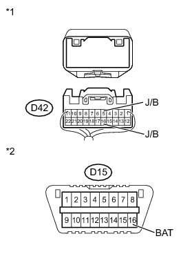
(b) Disconnect the D42 P-CAN junction connector.
Text in Illustration
(c) Measure the resistance according to the value(s) in the table below.
Standard Resistance:
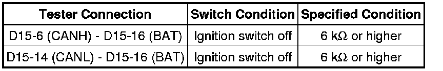
Text in Illustration

NG -- CONNECT CONNECTOR
OK -- Continue to next step.
4. CHECK CAN BUS LINE FOR SHORT TO +B (P-CAN J/C - POWER STEERING ECU)
(a) Measure the resistance according to the value(s) in the table below.

HINT
The resistance must be measured after the D42 P-CAN junction connector is disconnected.
Standard Resistance:

Text in Illustration

NG -- CHECK CAN BUS LINE FOR SHORT TO +B (POWER STEERING ECU MAIN WIRE)
OK -- Continue to next step.
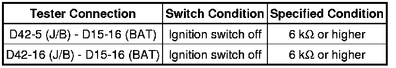
5. CHECK CAN BUS LINE FOR SHORT TO +B (P-CAN J/C - MAIN BODY ECU)
(a) Measure the resistance according to the value(s) in the table below.
HINT
The resistance must be measured after the D42 P-CAN junction connector is disconnected.
Standard Resistance:

Text in Illustration

NG -- CHECK CAN BUS LINE FOR SHORT TO +B (MAIN BODY ECU BRANCH WIRE)
OK -- Continue to next step.
6. CHECK CAN BUS LINE FOR SHORT TO +B (P-CAN J/C - YAW RATE SENSOR)
HINT
For vehicles without VSC, go to step 7.
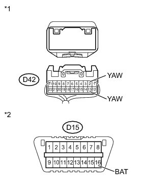
(a) Measure the resistance according to the value(s) in the table below.
HINT
The resistance must be measured after the D42 P-CAN junction connector is disconnected.
Standard Resistance:
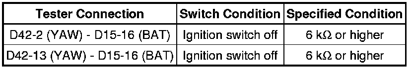
Text in Illustration

NG -- CHECK CAN BUS LINE FOR SHORT TO +B (YAW RATE SENSOR BRANCH WIRE)
OK -- Continue to next step.
7. CHECK CAN BUS LINE FOR SHORT TO +B (P-CAN J/C - COMBINATION METER ECU)
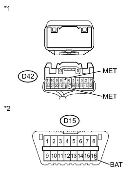
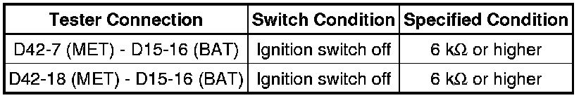
(a) Measure the resistance according to the value(s) in the table below.
HINT
The resistance must be measured after the D42 P-CAN junction connector is disconnected.
Standard Resistance:

Text in Illustration

NG -- CHECK CAN BUS LINE FOR SHORT TO +B (COMBINATION METER ECU BRANCH WIRE)
OK -- REPAIR OR REPLACE CAN MAIN WIRE OR CONNECTOR (P-CAN J/C - D-CAN J/C (CAN-H, CAN-L))
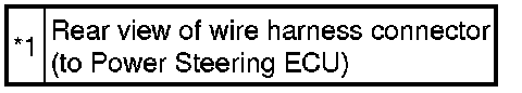
8. CHECK CAN BUS LINE FOR SHORT TO +B (POWER STEERING ECU MAIN WIRE)
(a) Disconnect the D31 power steering ECU connector.
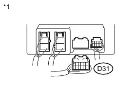
Text in Illustration
(b) Measure the resistance according to the value(s) in the table below.
HINT
The resistance must be measured after the D42 P-CAN junction connector is disconnected.
Standard Resistance:
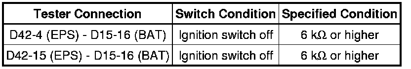
Text in Illustration

Result
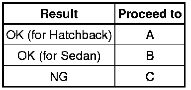
C -- REPAIR OR REPLACE CAN MAIN WIRE CONNECTED TO POWER STEERING ECU (CAN-H, CAN-L)
B -- REPLACE POWER STEERING ECU Removal
A -- REPLACE POWER STEERING ECU Removal
9. CHECK CAN BUS LINE FOR SHORT TO +B (MAIN BODY ECU BRANCH WIRE)
(a) Disconnect the D33 main body ECU connector.
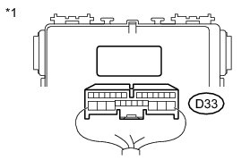
Text in Illustration
(b) Measure the resistance according to the value(s) in the table below.
HINT
The resistance must be measured after the D42 P-CAN junction connector is disconnected.
Standard Resistance:
Text in Illustration

NG -- REPAIR OR REPLACE CAN BRANCH WIRE CONNECTED TO MAIN BODY ECU (CAN-H, CAN-L)
OK -- REPLACE MAIN BODY ECU
10. CHECK CAN BUS LINE FOR SHORT TO +B (YAW RATE SENSOR BRANCH WIRE)
(a) Disconnect the D81 yaw rate sensor connector.
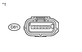
Text in Illustration
(b) Measure the resistance according to the value(s) in the table below.
HINT
The resistance must be measured after the D42 P-CAN junction connector is disconnected.
Standard Resistance:

Text in Illustration

NG -- REPAIR OR REPLACE CAN BRANCH WIRE CONNECTED TO YAW RATE SENSOR (CAN-H, CAN-L)
OK -- REPLACE YAW RATE SENSOR Removal
11. CHECK CAN BUS LINE FOR SHORT TO +B (COMBINATION METER ECU BRANCH WIRE)
(a) Disconnect the D1 Combination meter ECU connector.
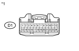
Text in Illustration
(b) Measure the resistance according to the value(s) in the table below.
HINT
The resistance must be measured after the D42 P-CAN junction connector is disconnected.
Standard Resistance:
Text in Illustration
Result

C -- REPAIR OR REPLACE CAN BRANCH WIRE CONNECTED TO COMBINATION METER ECU (CAN-H, CAN-L)
B -- REPLACE COMBINATION METER ECU Removal
A -- REPLACE COMBINATION METER ECU Removal
12. CONNECT CONNECTOR
(a) Reconnect the P-CAN junction connector.
NEXT -- Continue to next step.
13. CHECK CAN BUS LINE FOR SHORT TO +B (D-CAN J/C - ECM)
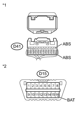
(a) Disconnect the D41 D-CAN junction connector.

(b) Measure the resistance according to the value(s) in the table below.
Standard Resistance:
Text in Illustration

NG -- CHECK CAN BUS LINE FOR SHORT TO +B (ECM MAIN WIRE)
OK -- Continue to next step.
14. CHECK CAN BUS LINE FOR SHORT TO +B (D-CAN J/C - BRAKE ACTUATOR (SKID CONTROL ECU))
HINT
For vehicles without ABS, go to step 15.
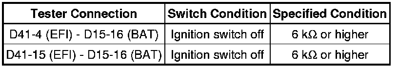
(a) Measure the resistance according to the value(s) in the table below.
HINT
The resistance must be measured after the D41 D-CAN junction connector is disconnected.
Standard Resistance:

Text in Illustration

NG -- CHECK CAN BUS LINE FOR SHORT TO +B (BRAKE ACTUATOR (SKID CONTROL ECU) BRANCH WIRE)
OK -- Continue to next step.
15. CHECK CAN BUS LINE FOR SHORT TO +B (D-CAN J/C - ABS AND TRACTION ACTUATOR (SKID CONTROL ECU))
HINT
For vehicles without VSC, go to step 17.
(a) Measure the resistance according to the value(s) in the table below.
HINT
The resistance must be measured after the D41 D-CAN junction connector is disconnected.
Standard Resistance:
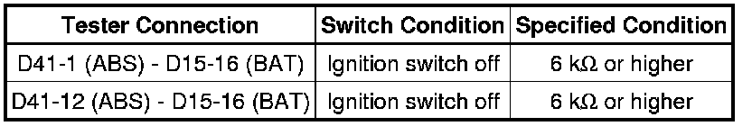
Text in Illustration
NG -- CHECK CAN BUS LINE FOR SHORT TO +B (ABS AND TRACTION ACTUATOR (SKID CONTROL ECU) BRANCH WIRE)
OK -- Continue to next step.