Part 1
1NZ-FE ENGINE CONTROL SYSTEM: SFI SYSTEM: EVAP System
- EVAP System
RELATED DTCS
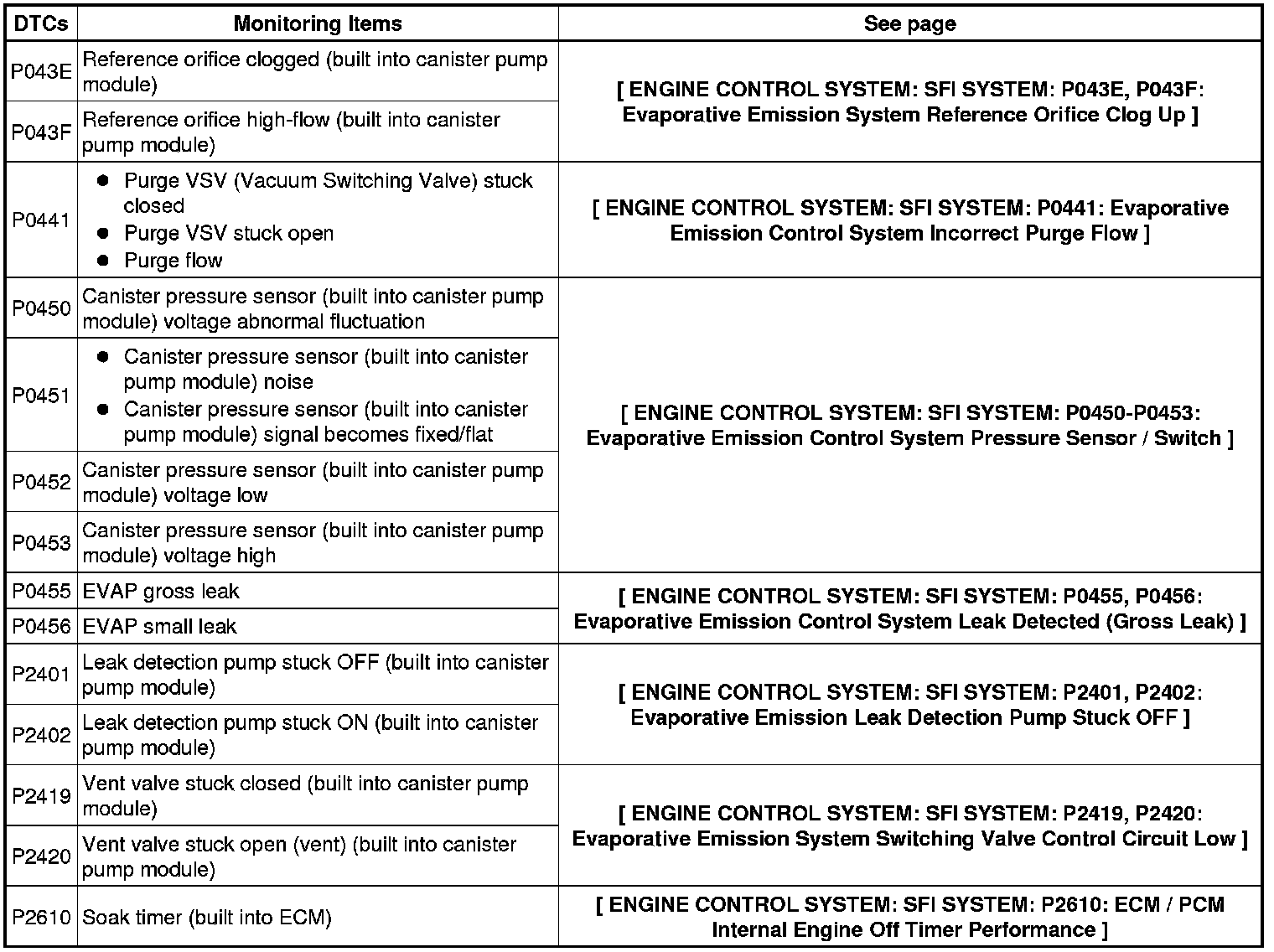
If any EVAP system DTCs are set, the malfunctioning area can be determined using the table below.
NOTICE:
If the reference pressure difference between the first and second checks is greater than the specification, all the DTCs relating to the reference pressure (P043E, P043F, P2401, P2402 and P2419) are stored.
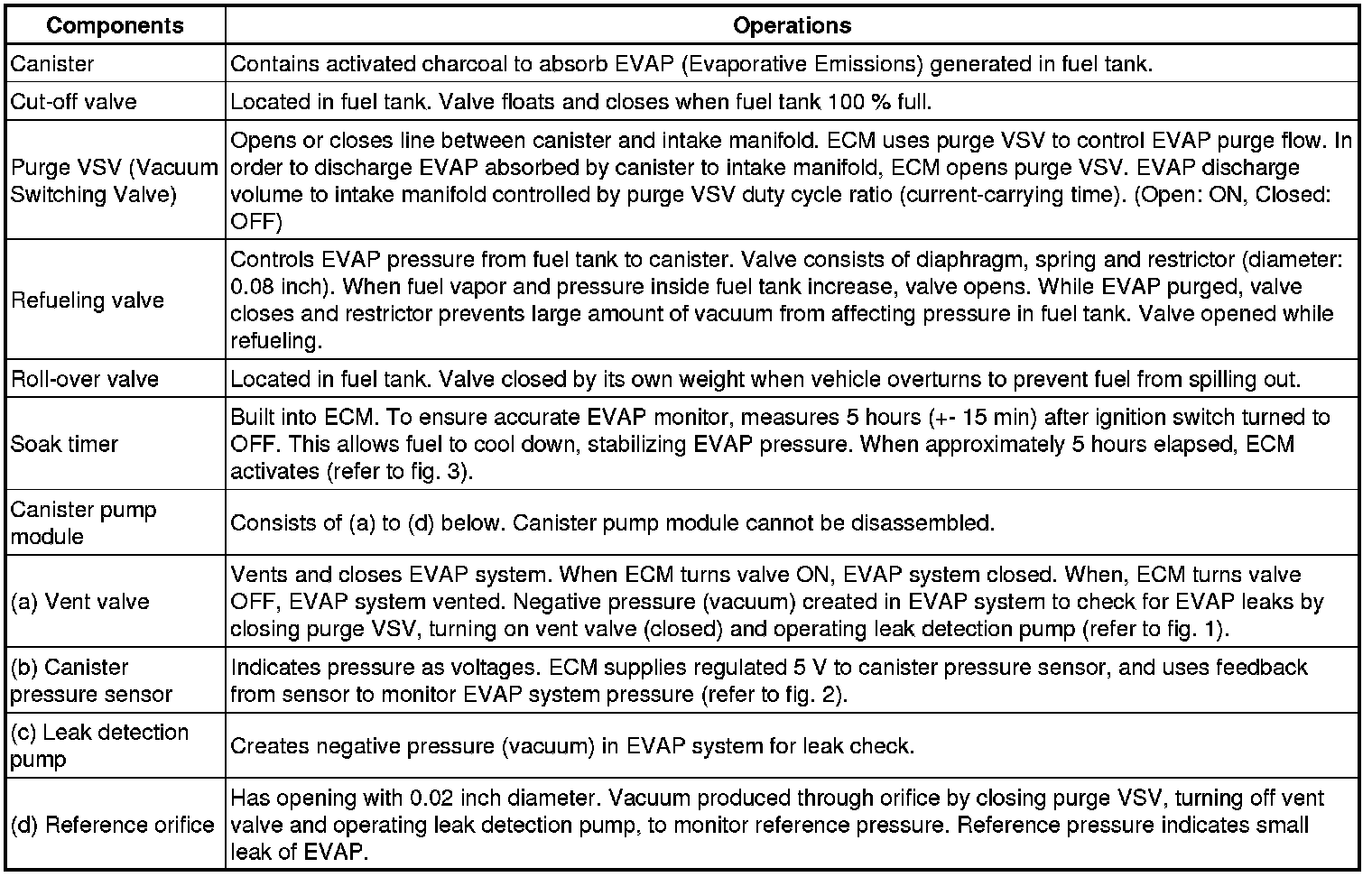
DESCRIPTION
NOTICE:
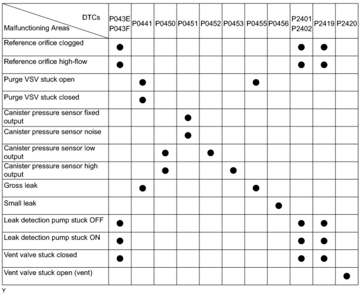
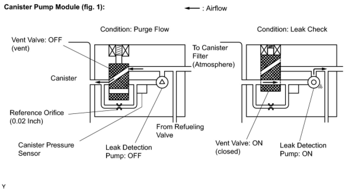
In this vehicle's EVAP system, turning ON the vent valve does not seal off the EVAP system. To check for leaks in the EVAP system, disconnect the air inlet vent hose and apply pressure from the atmospheric side of the canister.
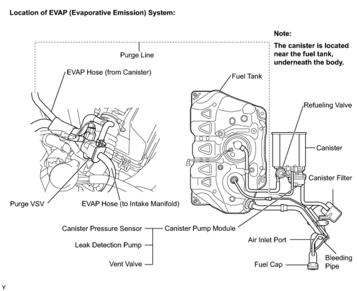
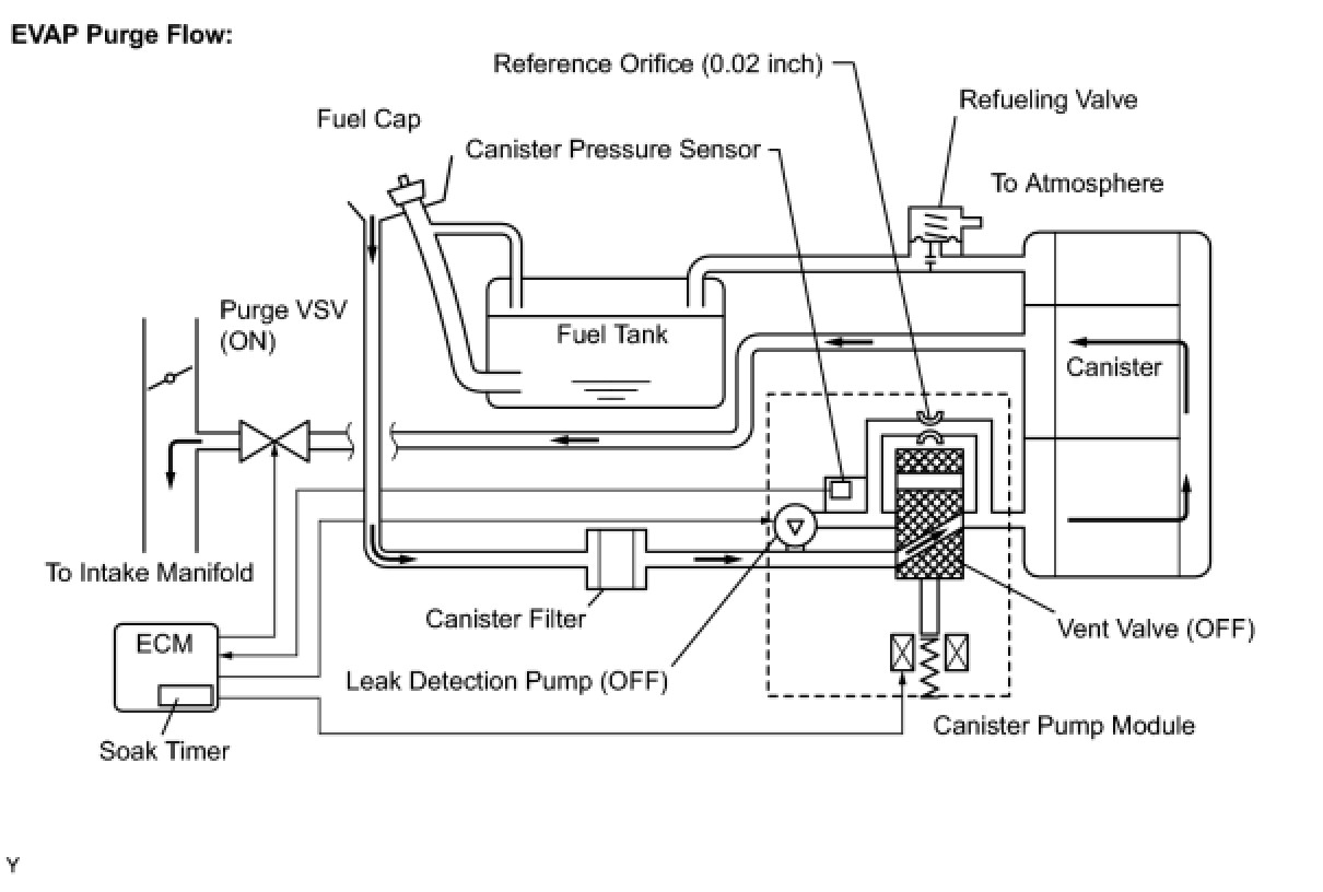
While the engine is running, if a predetermined condition (closed-loop etc.) is met, the purge VSV is opened by the ECM and stored fuel vapors in the canister are purged into the intake manifold. The ECM changes the duty cycle ratio of the purge VSV to control purge flow volume.
The purge flow volume is also determined by the intake manifold pressure. Atmospheric pressure is allowed into the canister through the vent valve to ensure that the purge flow is maintained when the negative pressure (vacuum) is applied to the canister.
The following two monitors run to confirm the appropriate EVAP system operation.
1. Key-off monitor
This monitor checks for EVAP (Evaporative Emission) system leaks and canister pump module malfunctions. The monitor starts 5 hours* after the ignition switch is turned to OFF. At least 5 hours are required for the fuel to cool down to stabilize the EVAP pressure, thus making the EVAP system monitor more accurate.
The leak detection pump creates negative pressure (vacuum) in the EVAP system and the pressure is measured. Finally, the ECM monitors for leaks from the EVAP system, and malfunctions in both the canister pump module and purge VSV, based on the EVAP pressure.
HINT
*: If the engine coolant temperature is not below 35°C (95°F) 5 hours after the ignition switch is turned off, the monitor check starts 2 hours later. If it is still not below 35°C (95°F) 7 hours after the ignition switch is turned off, the monitor check starts 2.5 hours later.
2. Purge flow monitor
The purge flow monitor consists of the two monitors. The 1st monitor is conducted every time and the 2nd monitor is activated if necessary.
* The 1st monitor
While the engine is running and the purge VSV (Vacuum Switching Valve) is ON (open), the ECM monitors the purge flow by measuring the EVAP pressure change. If negative pressure is not created, the ECM begins the 2nd monitor.
* The 2nd monitor
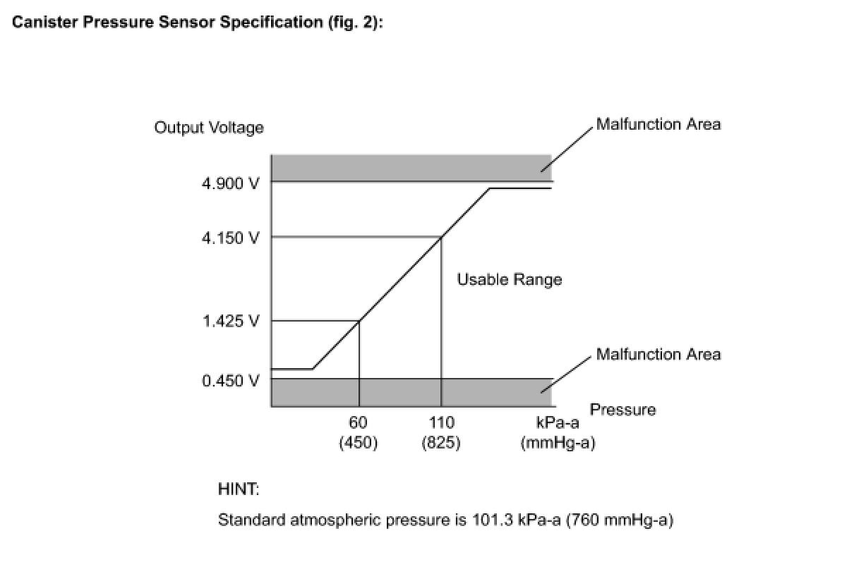
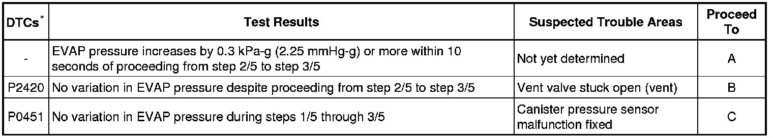
The vent valve is turned OFF (open) and the EVAP pressure is measured. If the variation in the pressure is less than 0.5 kPa-g (3.75 mmHg-g), the ECM interprets this as the purge VSV being stuck closed, and illuminates the MIL and sets DTC P0441 (2 trip detection logic).
Atmospheric pressure check:
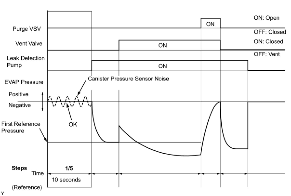
In order to ensure reliable malfunction detection, the variation between the atmospheric pressures, before and after conduction of the purge flow monitor, is measured by the ECM.
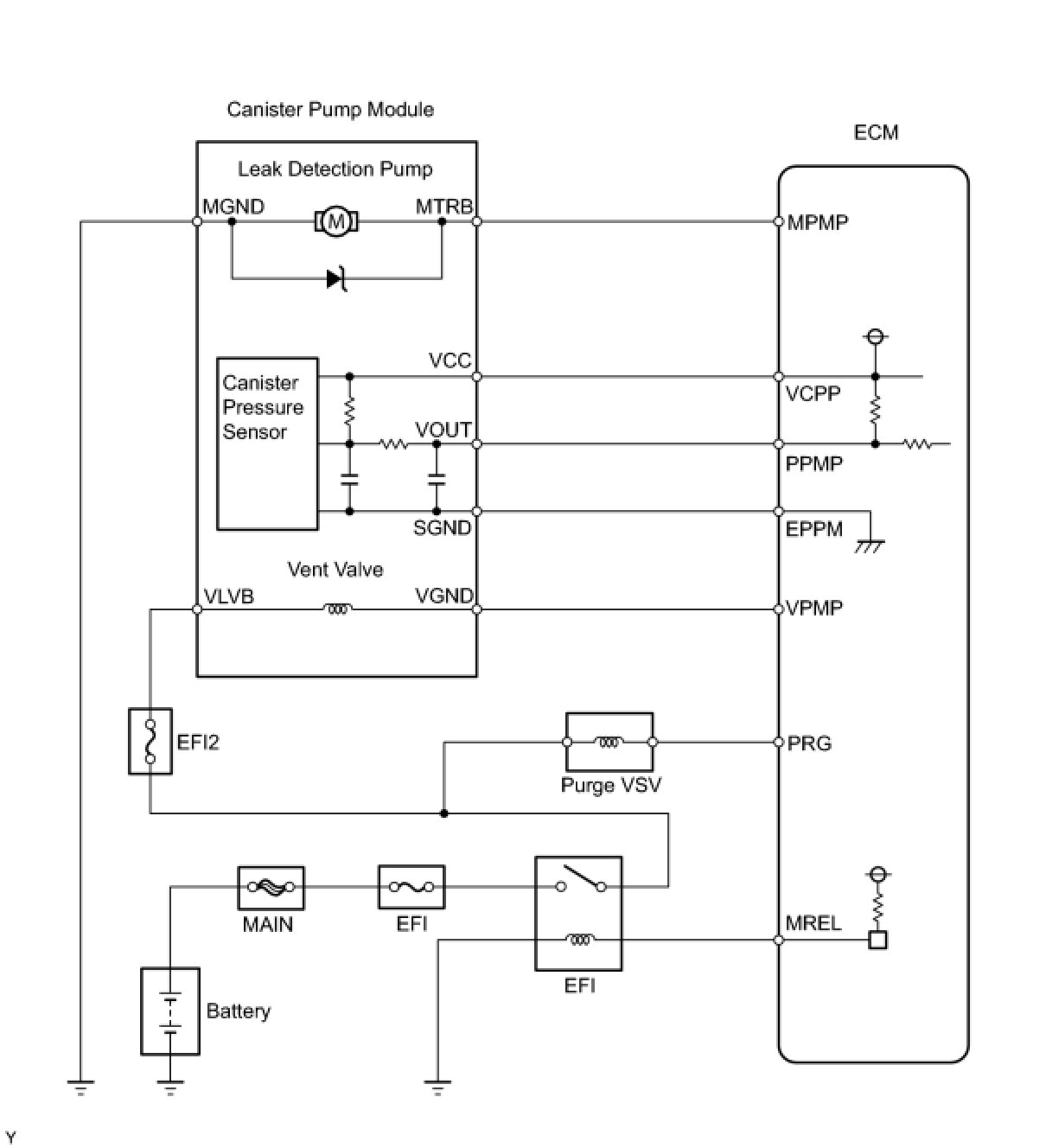
WIRING DIAGRAM
INSPECTION PROCEDURE
NOTICE:
An intelligent tester is required to conduct the following diagnostic troubleshooting procedure.
HINT
* Using intelligent tester monitor results enables the EVAP (Evaporative Emission) system to be confirmed.
* Read freeze frame data using an intelligent tester. Freeze frame data record the engine condition when malfunctions are detected. When troubleshooting, freeze frame data can help determine if the vehicle was moving or stationary, if the engine was warmed up or not, if the air-fuel ratio was lean or rich, and other data, from the time the malfunction occurred.
PROCEDURE
1. CONFIRM DTC
(a) Turn the ignition switch to OFF and wait for 10 seconds.
(b) Turn the ignition switch to ON.
(c) Turn the ignition switch to OFF and wait for 10 seconds.
(d) Connect an intelligent tester to the DLC3.
(e) Turn the ignition switch to ON and turn the tester ON.
(f) Select the following menu items: DIAGNOSIS / ENHANCED OBD II / DTC INFO / CURRENT CODES.
(g) Confirm DTCs and freeze frame data.
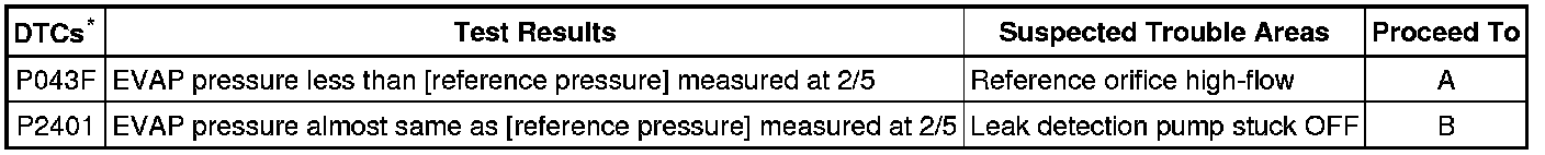
If any EVAP system DTCs are set, the malfunctioning area can be determined using the table below.
NOTICE:
If the reference pressure difference between the first and second checks is greater than the specification, all the DTCs relating to the reference pressure (P043E, P043F, P2401, P2402 and P2419) are stored.
NEXT -- Continue to next step.
2. PERFORM EVAP SYSTEM CHECK (AUTO OPERATION)
NOTICE:
* The EVAP SYSTEM CHECK (AUTO OPERATION) consists of five steps performed automatically by the intelligent tester. It takes a maximum of approximately 18 minutes.
* Do not perform the EVAP SYSTEM CHECK when the fuel tank is more than 90% full because the cut-off valve may be closed, making the fuel tank leak check unavailable.
* Do not run the engine during this operation.
* When the temperature of the fuel is 35°C (95°F) or more, a large amount of vapor forms and any check results become inaccurate. When performing the EVAP SYSTEM CHECK, keep the temperature below 35°C (95°F).
(a) Clear DTCs Reading and Clearing Diagnostic Trouble Codes.
(b) On the tester, select the following menu items: DIAGNOSIS / ENHANCED OBD II / SYSTEM CHECK / EVAP SYS CHECK / AUTO OPERATION.
(c) After the EVAP SYSTEM CHECK is completed, check for pending DTCs by selecting the following menu items: DIAGNOSIS / ENHANCED OBD II / DTC INFO / PENDING CODES.
HINT
If no pending DTCs are displayed, perform the MONITOR CONFIRMATION (see "Diagnostic Help" menu). After this confirmation, check for pending DTCs. If no DTCs are displayed, the EVAP system is normal.
NEXT -- Continue to next step.
3. PERFORM EVAP SYSTEM CHECK (MANUAL OPERATION)
NOTICE:
* In the EVAP SYSTEM CHECK (MANUAL OPERATION), perform the series of 5 EVAP SYSTEM CHECK steps manually using the intelligent tester.
* Do not perform the EVAP SYSTEM CHECK when the fuel tank is more than 90% full because the cut-off valve may be closed, making the fuel tank leak check unavailable.
* Do not run the engine during this operation.
* When the temperature of the fuel is 35°C (95°F) or more, a large amount of vapor forms and any check results become inaccurate. When performing the EVAP SYSTEM CHECK, keep the temperature below 35°C (95°F).
(a) Clear DTCs Reading and Clearing Diagnostic Trouble Codes.
(b) Select the following menu items: DIAGNOSIS / ENHANCED OBD II / SYSTEM CHECK / EVAP SYS CHECK / MANUAL OPERATION.
NEXT -- Continue to next step.
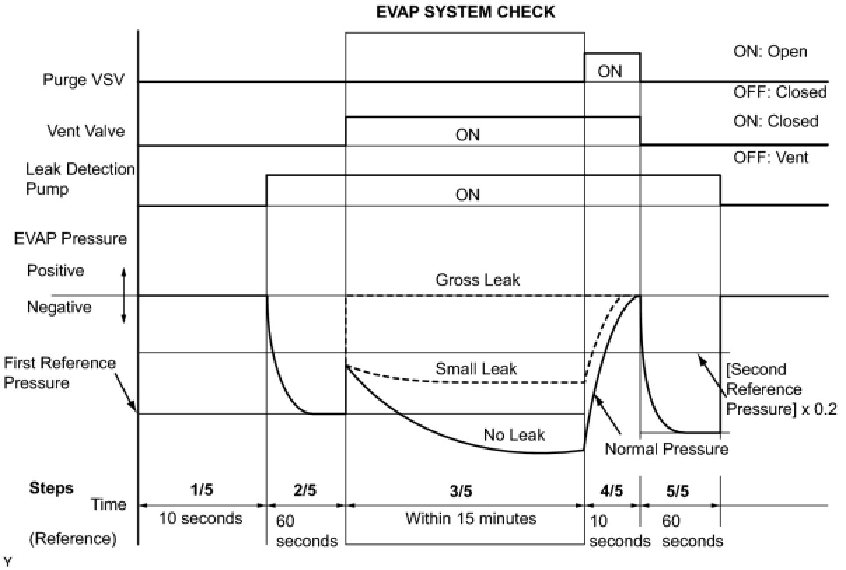
4. PERFORM EVAP SYSTEM CHECK (STEP 1/5)
(a) Check the EVAP pressure in step 1/5.
Result:
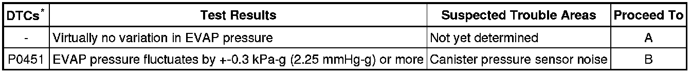
*: These DTCs are already present in the ECM when the vehicle arrives and are confirmed in step 1.
B -- REPLACE CHARCOAL CANISTER ASSEMBLY
A -- Continue to next step.
5. PERFORM EVAP SYSTEM CHECK (STEP 1/5 TO 2/5)
(a) Check the EVAP pressure in steps 1/5 and 2/5.
Result:
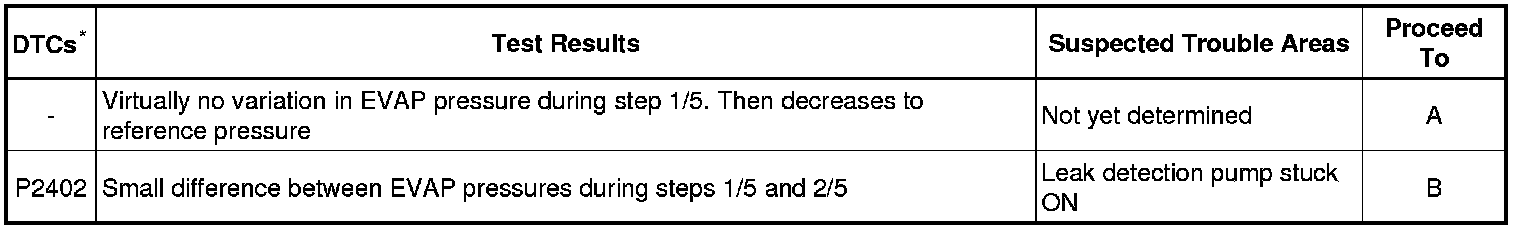
*: These DTCs are already present in the ECM when the vehicle arrives and are confirmed in step 1.
HINT
The first reference pressure is the value determined in step 2/5.
B -- PERFORM ACTIVE TEST USING INTELLIGENT TESTER (VACUUM PUMP (ALONE))
A -- Continue to next step.
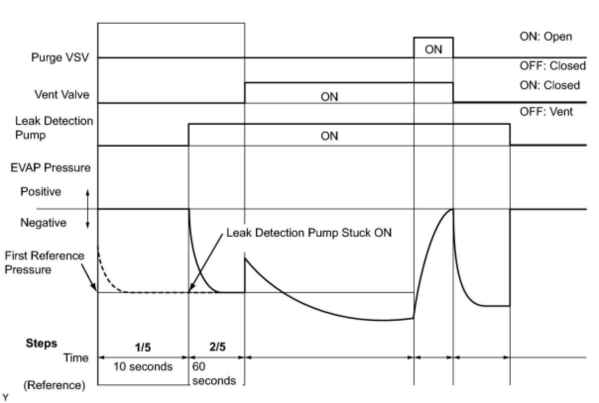
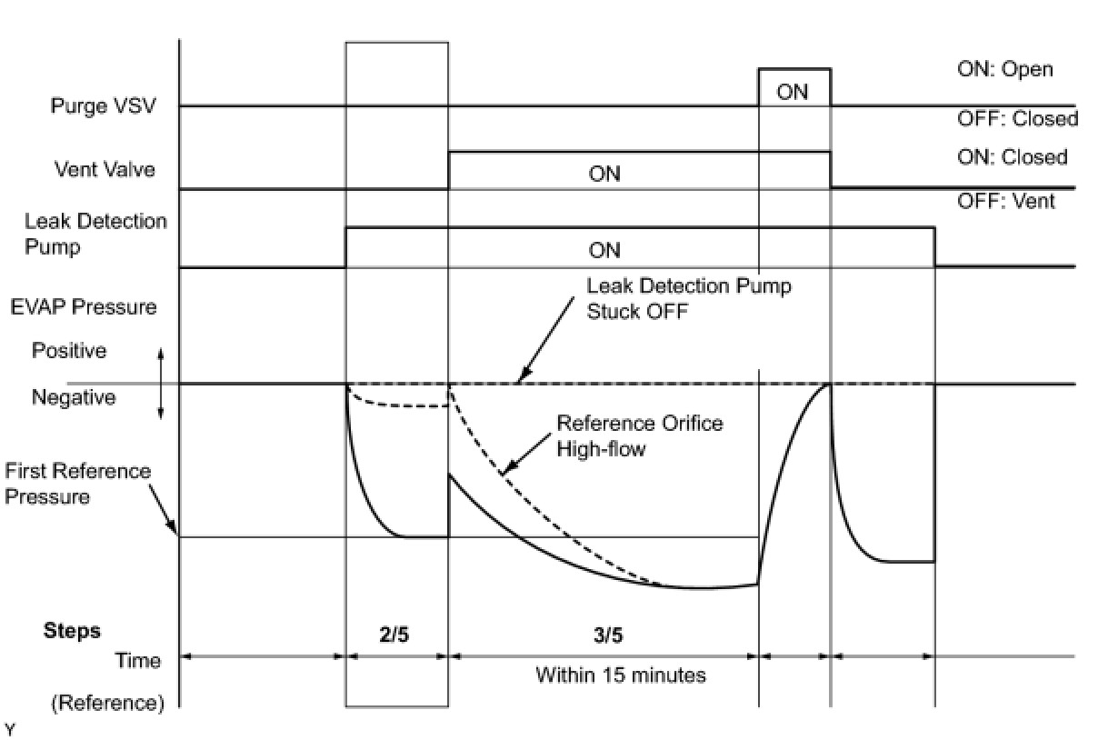
6. PERFORM EVAP SYSTEM CHECK (STEP 2/5)
HINT
Make a note of the pressures checked in steps (a) and (b) below.
(a) Check the EVAP pressure 4 seconds after the leak detection pump is activated*.
*: The leak detection pump begins to operate as step 1/5 finishes and step 2/5 starts.
(b) Check the EVAP pressure again when it has stabilized. This pressure is the reference pressure.
Result:
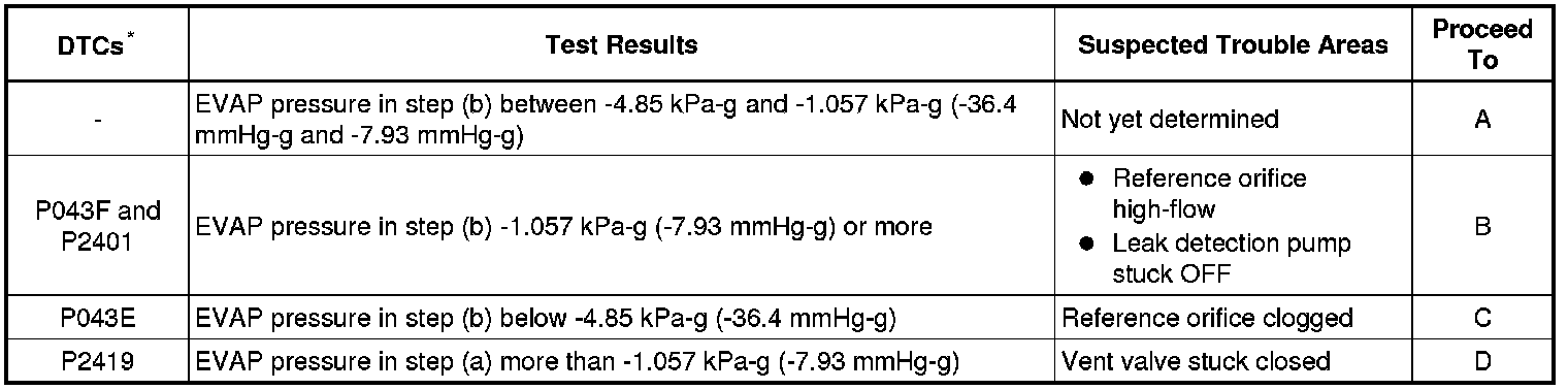
*: These DTCs are already present in the ECM when the vehicle arrives and are confirmed in step 1.
B -- PERFORM EVAP SYSTEM CHECK (STEP 3/5)
C -- REPLACE CHARCOAL CANISTER ASSEMBLY
D -- INSPECT CANISTER PUMP MODULE (VENT VALVE OPERATION)
A -- Continue to next step.
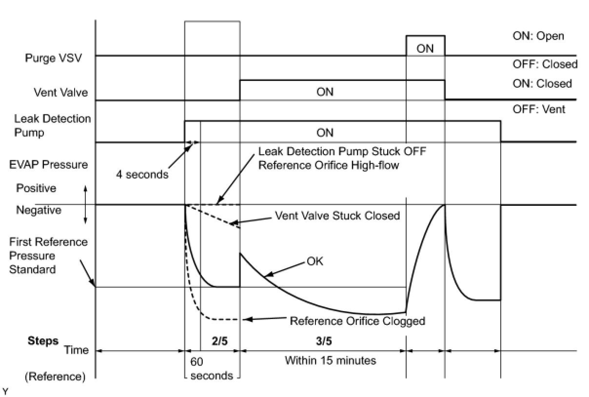
7. PERFORM EVAP SYSTEM CHECK (STEP 2/5 TO 3/5)
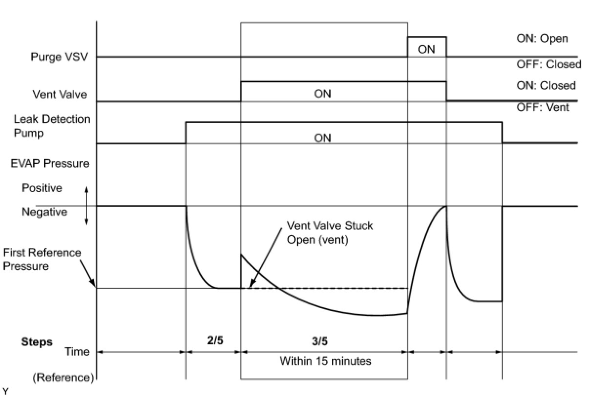
(a) Check the EVAP pressure increase in step 3/5.
Result:
*: These DTCs are already present in the ECM when the vehicle arrives and are confirmed in step 1.
B -- INSPECT CANISTER PUMP MODULE (POWER SOURCE FOR VENT VALVE)
C -- REPLACE CHARCOAL CANISTER ASSEMBLY
A -- Continue to next step.
8. PERFORM EVAP SYSTEM CHECK (STEP 3/5)
(a) Wait until the EVAP pressure change is less than 0.1 kPa-g (0.75 mmHg-g) for 30 seconds.
(b) Measure the EVAP pressure and record it.
HINT
A few minutes are required for the EVAP pressure to become saturated. When there is little fuel in the fuel tank, it takes up to 15 minutes.
NEXT -- Continue to next step.
9. PERFORM EVAP SYSTEM CHECK (STEP 4/5)
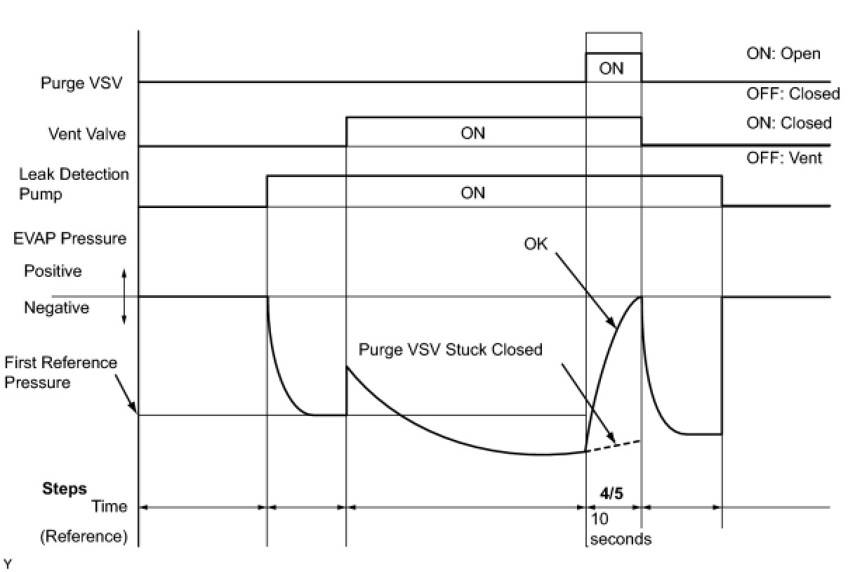
(a) Check the EVAP pressure in step 4/5.
Result:
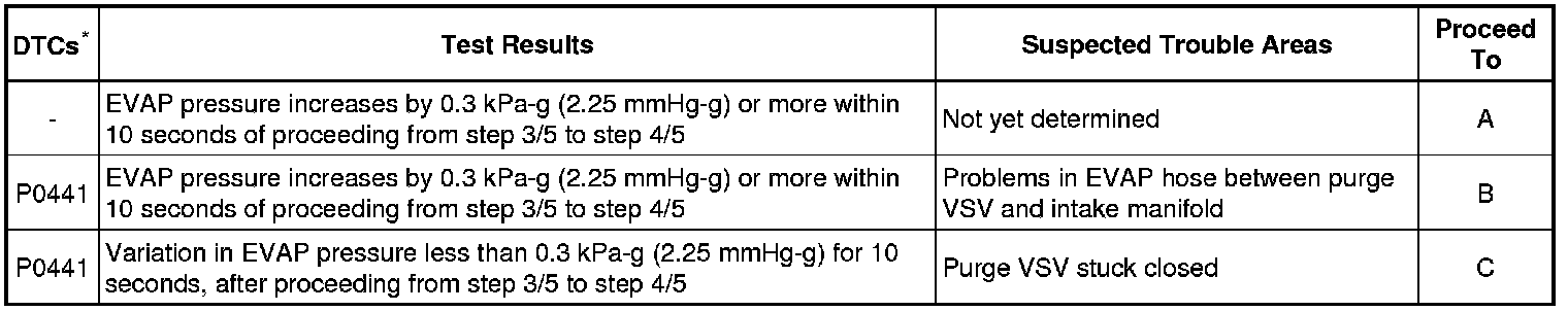
*: These DTCs are already present in the ECM when the vehicle arrives and are confirmed in step 1.
B -- CHECK EVAP HOSE (PURGE VSV - INTAKE MANIFOLD)
C -- PERFORM ACTIVE TEST USING INTELLIGENT TESTER (PURGE VSV)
A -- Continue to next step.
10. PERFORM EVAP SYSTEM CHECK (STEP 5/5)
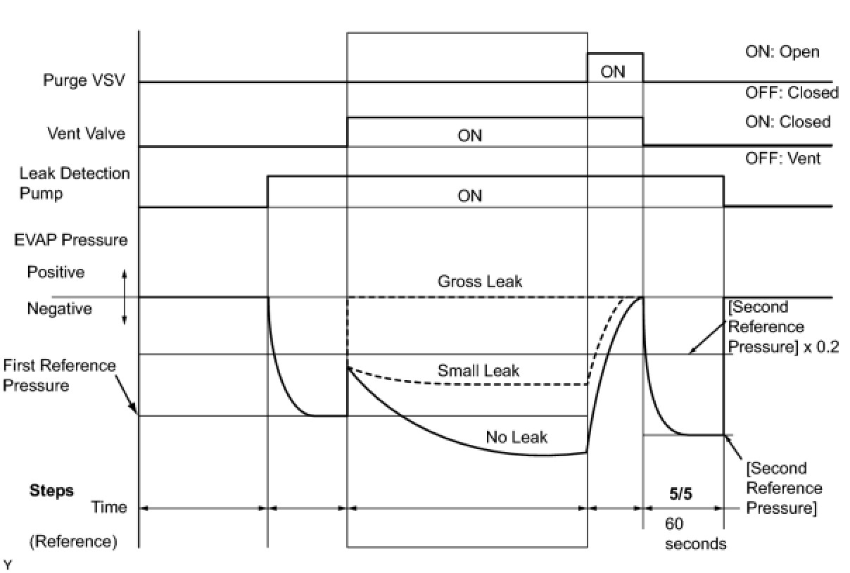
(a) Check the EVAP pressure in step 5/5.
(b) Compare the EVAP pressure in step 3/5 and the second reference pressure (step 5/5).
Result:
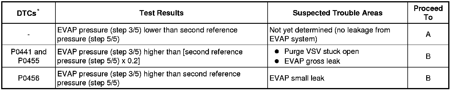
*: These DTCs are already present in the ECM when the vehicle arrives and are confirmed in step 1.
A -- REPAIR OR REPLACE PARTS AND COMPONENTS INDICATED BY OUTPUT DTCS
B -- PERFORM ACTIVE TEST USING INTELLIGENT TESTER (PURGE VSV)
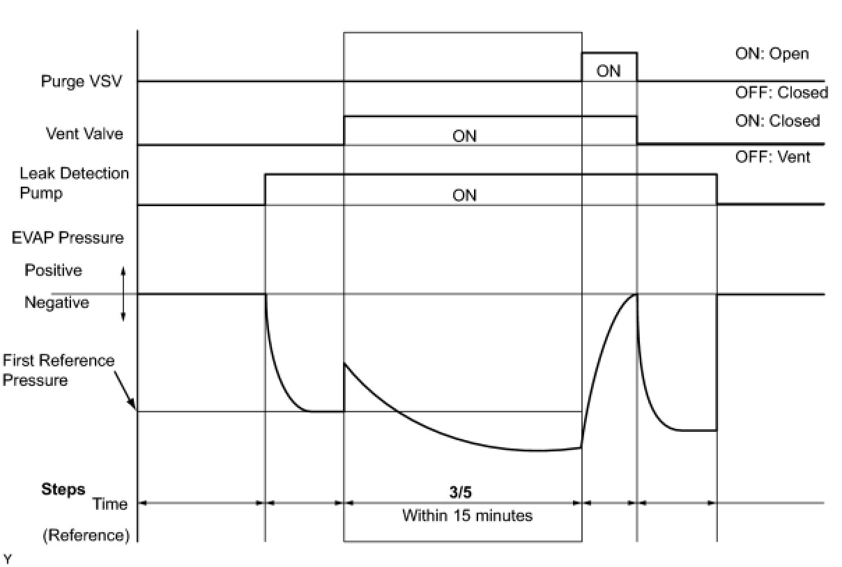
11. PERFORM EVAP SYSTEM CHECK (STEP 3/5)
(a) Check the EVAP pressure in step 3/5.
Result:
*: These DTCs are already present in the ECM when the vehicle arrives and are confirmed in step 1.
HINT
The first reference pressure is the value determined in step 2/5.
A -- REPLACE CHARCOAL CANISTER ASSEMBLY
B -- PERFORM ACTIVE TEST USING INTELLIGENT TESTER (VACUUM PUMP (ALONE))
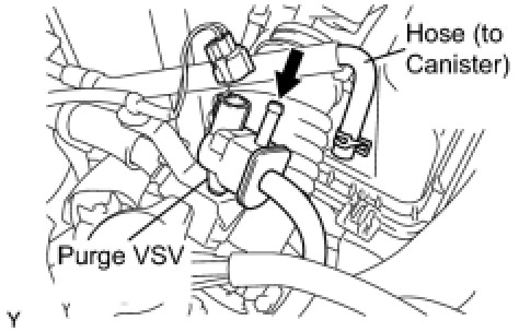
12. PERFORM ACTIVE TEST USING INTELLIGENT TESTER (PURGE VSV)
(a) On the intelligent tester, select the following menu items: DIAGNOSIS / ENHANCED OBD II / ACTIVE TEST / EVAP VSV.
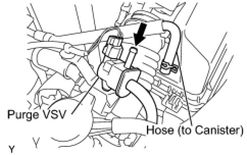
(b) Disconnect the hose (connected to the canister) from the purge VSV.
(c) Start the engine.
(d) Using the tester, turn off the purge VSV (EVAP VSV: OFF).
(e) Use your finger to confirm that the purge VSV has no suction.
(f) Using the tester, turn on the purge VSV (EVAP VSV: ON).
(g) Use your finger to confirm that the purge VSV has suction.
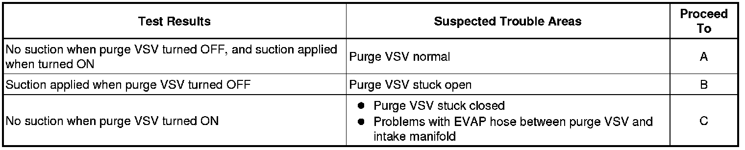
Result:
(h) Reconnect the hose.
B -- INSPECT DUTY VACUUM SWITCHING VALVE (PURGE VSV)
C -- CHECK EVAP HOSE (PURGE VSV - INTAKE MANIFOLD)
A -- Continue to next step.
13. CHECK FUEL CAP ASSEMBLY
(a) Check that the fuel cap is correctly installed and confirm the fuel cap meets OEM specifications.
(1) Tighten the fuel cap until a few click sounds are heard.
HINT
If an EVAP tester is available, check the fuel cap using the tester.
(b) Remove the fuel cap and install it onto a fuel cap adapter.
(c) Connect an EVAP tester pump hose to the adapter, and pressurize the cap to 3.2 to 3.7 kPa (24 to 28 mmHg) using an EVAP tester pump.
(d) Seal the adapter and wait for 2 minutes.
(e) Check the pressure. If the pressure is 2 kPa (15 mmHg) or more, the fuel cap is normal.
Result:
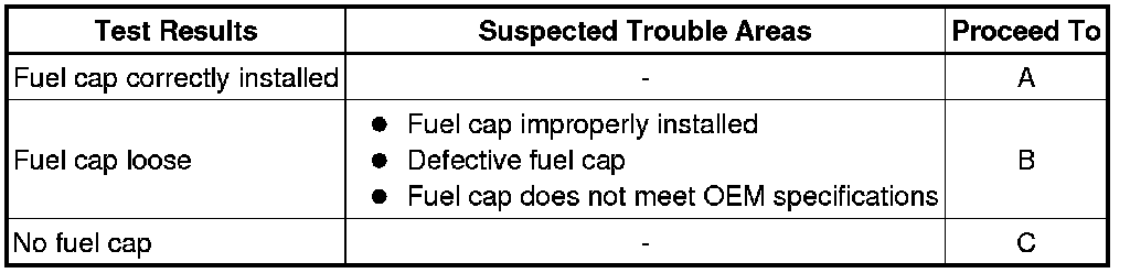
(f) Reinstall the fuel cap.
A -- LOCATE EVAP LEAK PART
B -- CORRECTLY REINSTALL OR REPLACE FUEL CAP
C -- REPLACE FUEL CAP
14. INSPECT DUTY VACUUM SWITCHING VALVE (PURGE VSV)
(a) Turn the ignition switch to OFF.
(b) Disconnect the C3 purge VSV connector.
(c) Disconnect the hose (connected to the canister) from the purge VSV.
(d) Start the engine.
(e) Use your finger to confirm that the purge VSV has no suction.
Result:
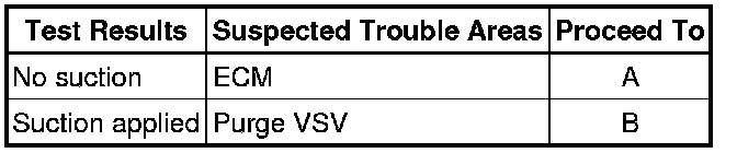
(f) Reconnect the purge VSV connector.
(g) Reconnect the hose.
A -- REPLACE ECM
B -- REPLACE DUTY VACUUM SWITCHING VALVE (PURGE VSV)
15. CHECK EVAP HOSE (PURGE VSV - INTAKE MANIFOLD)
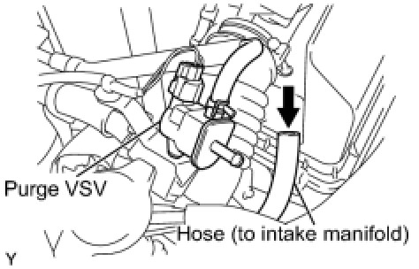
(a) Disconnect the hose (connected to the intake manifold) from the purge VSV.
(b) Start the engine.
(c) Use your finger to confirm that the hose has suction.
Result:
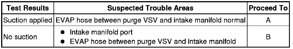
(d) Reconnect the hose.
B -- INSPECT INTAKE MANIFOLD (EVAP PURGE PORT)
A -- Continue to next step.
16. INSPECT DUTY VACUUM SWITCHING VALVE (PURGE VSV)
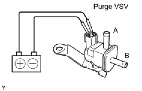
(a) Remove the purge VSV.
(b) Apply the battery voltage to the terminals of the purge VSV.
(c) Using an air gun, confirm that air flows from port A to port B.
Result:
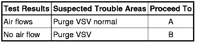
(d) Install the purge VSV.
B -- REPLACE DUTY VACUUM SWITCHING VALVE (PURGE VSV)
A -- Continue to next step.
17. CHECK HARNESS AND CONNECTOR (POWER SOURCE OF PURGE VSV)
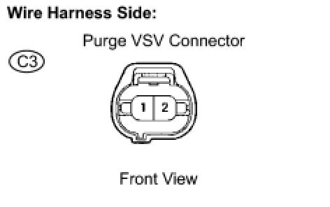
(a) Disconnect the C3 purge VSV connector.
(b) Turn the ignition switch to ON.
(c) Measure the voltage between terminal 2 of the purge VSV connector and the body ground.
Result:
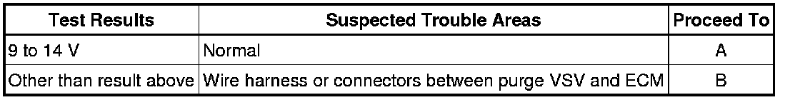
(d) Reconnect the purge VSV connector.
B -- REPAIR OR REPLACE HARNESS OR CONNECTOR
A -- Continue to next step.