Service Procedure
FIGURE 1 - CATALYTIC CONVERTER:
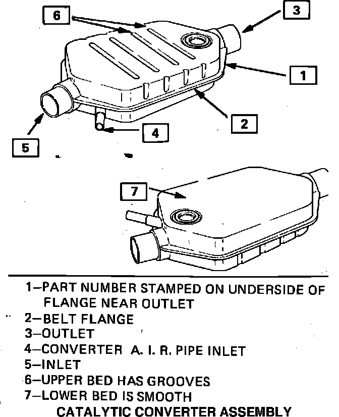
PART I - INSPECTION
1. Raise vehicle on hoist.
2. Refer to Figure 1 for location of catalytic converter part number.
3a. The converter need not be replaced if it is the single bed bead
converter Part Number 25056364 (Pontiac Dealer Bulletin 82-T-89) OR the dual bed bead converter Part Numbers 25056675 or 25056676 (Pontiac Dealer Bulletin 82-T-97). Proceed to PART III if the replacement of the converter is not required.
3b. If the converter part number is listed in Column 1 of the table below replace the converter with the appropriate converter part number identified in Column 2 of the table. (All vehicle models listed are equipped with RPO LG4 5.0 Liter engines).
Column 1 Column 2
Model Year Original Dual New Dual Bed
Vehicle Bed Bead Conv. Bead Conv.
1981 Firebird Formula model
8999588 25056674
with 4-Speed Manual Transmission
1981 Firebird Trans Am model 8999589 25056675
with 4-Speed Manual Transmission
1982 All Involved Firebirds 8999830 25056676
PART II - CONVERTER REMOVAL, PREPARATION AND INSTALLATION
1. Raise vehicle on hoist.
2. Disconnect air supply pipe from front of converter (Figure 1-Item 4).
3. Disconnect intermediate pipe from rear of converter (Figure 1-Item 3).
4. Disconnect hanger bracket from converter.
5. Loosen front exhaust clamp to remove converter from vehicle. Discard clamp.
6. Stand old converter upright on inlet end and pour two (2) 8 ounce cups of water into outlet end (Figure 1-Item 3) to control catalyst dust.
7. Using hammer and chisel, remove upper bed fill hole plug from old converter by driving chisel between the converter shell and rim of fill plug (Figure 1 - Items 6 and 7 for description of upper and lower beds). Deform fill plug until it can be removed with pliers.
8. Hold converter over a clean storage pan (J-34155-2) and empty catalyst beads by shaking and tapping converter belt flange (Figure 1-Item 2) with rubber mallet.
NOTICE: If upper bed is void or near void (a cup or less) of catalyst beads, the converter is considered damaged (internally) or expanded. Catalyst beads found in internally damaged or expanded converters are not to be used in new converters. These beads can be returned via exchange program described in WDDGM Bulletin IB No. 83-138.
9. Pour upper bed beads into sifting pan (J-34155-1). Sift out broken beads (smaller than half size) into a clean box. Pour sifted beads (half size and larger) into the other storage pan (J-34155-2). Set sifted beads aside for now.
Unusable beads and dust can be returned via exchange program described in WDDGM Bulletin IB No. 83-138.
10. Prop new converter up at a 45~ angle with upper bed fill hole at top. (See Figure 1-Items 6 and 7 for a description of upper and lower beds.)
FILLING THE UPPER BED WITH BEADS:
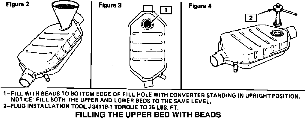
Tap funnel (J-34155-3) into converter fill hole with hammer (Figure 2).
11. Install packet of new upper bed beads from kit Part Number 25056590 into upper bed of the new converter.
12. Pour sifted upper bed beads (reference Step 9) or new upper beads, if required, into converter. Tap belt flange of the converter with rubber mallet to allow beads to settle. Continue filling and tapping until converter is full. See Figure 3-Item 1 for definition of full upper bed.
If upper bed is full, proceed to Step 13. If upper bed is not full, use leftover upper bed catalyst beads from involved dual bed converters to fill upper bed. If there are not enough used upper bed beads, obtain upper bed catalyst kit Part Number 25056680 and continue to fill upper bed until full.
NOTICE: Used upper bed beads (from non-damaged converters) are to be mixed with new upper bed beads. DO NOT MIX UPPER AND LOWER BEADS. Also, do not mix beads from converters of vehicles that are not involved. Store unused upper bed beads in a clean container marked "upper bed".
13. Lay converter down on a flat surface with upper bed on top.
14. Insert fill plug, Part Number 8998202, (two are provided in kit Part Number 25056590) into upper bed fill hole. If outer rim of the fill plug doesn't fit flat against converter shell, remove enough beads so it does.
15. With fill plug in fill hole, insert tool (J-34118) into fill plug (Figure 4-Item 2). Tighten tool to 35 ft.lbs. (47 N-m) and make sure plug outer rim is flat and tight against converter shell. Set new converter aside.
16. Remove lower bed plug from old converter using procedure described in Step 7.
FIGURE 1 - CATALYTIC CONVERTER:
FILLING THE UPPER BED WITH BEADS:
17. Hold converter over a clean storage pan (J-34155-2) and empty catalyst beads by shaking and tapping converter belt flange (Figure 1-Item 2) with rubber mallet.
18. Sift lower bed beads using procedure described in Step 9.
19. Prop new converter up at 45~ angle with lower bed fill hole at top (see Figure 1-Items 6 and 7 for definition of upper and lower beds). Tap funnel (J-34155-3) into converter fill hole with hammer (Figure 2).
20. Pour sifted lower bed beads (ref. Step 18) or new lower bed beads, if required, into new converter lower bed. Tap belt flange with rubber mallet to allow beads to settle. Continue filling and tapping until converter is full (ref. Figure 3-Item 1).
If lower bed is not full, use leftover lower bed catalyst beads saved from involved dual bed converters to fill lower bed. If there are not enough used lower bed beads, obtain lower bed bead service kit Part Number 25056682 (zone approval is required to obtain this kit), and continue filling the lower bed until full.
NOTICE: The leftover lower bed beads are to be saved for future use. Store them in a clean container marked "lower bed". DO NOT MIX UPPER AND LOWER BEADS. Also do not mix beads from converters off of vehicles that are not involved.
21. Lay converter down on flat surface with lower bed on top and install fill plug using procedure described in Steps 14 and 15.
22. Install new converter on vehicle reversing removal procedures described in this bulletin and referencing appropriate service manual.
Campaign Identification Label:
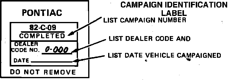
PART III - INSTALLATION OF CAMPAIGN IDENTIFICATION LABEL
Each vehicle modified in accordance with the instructions outlined in this service procedure will require a campaign identification label. Each label provides a space to include the campaign number, the five-digit dealer code of the dealer performing the campaign service, and the date vehicle was campaigned. This information may be inserted
with a typewriter or ballpoint pen. Install the label on the radiator baffle where it is readily visible. Close hood. (Additional campaign labels are available on stationery order as Form 7901-709.)