System Specifications
SERVICE DATA AND SPECIFICATIONS (SDS)
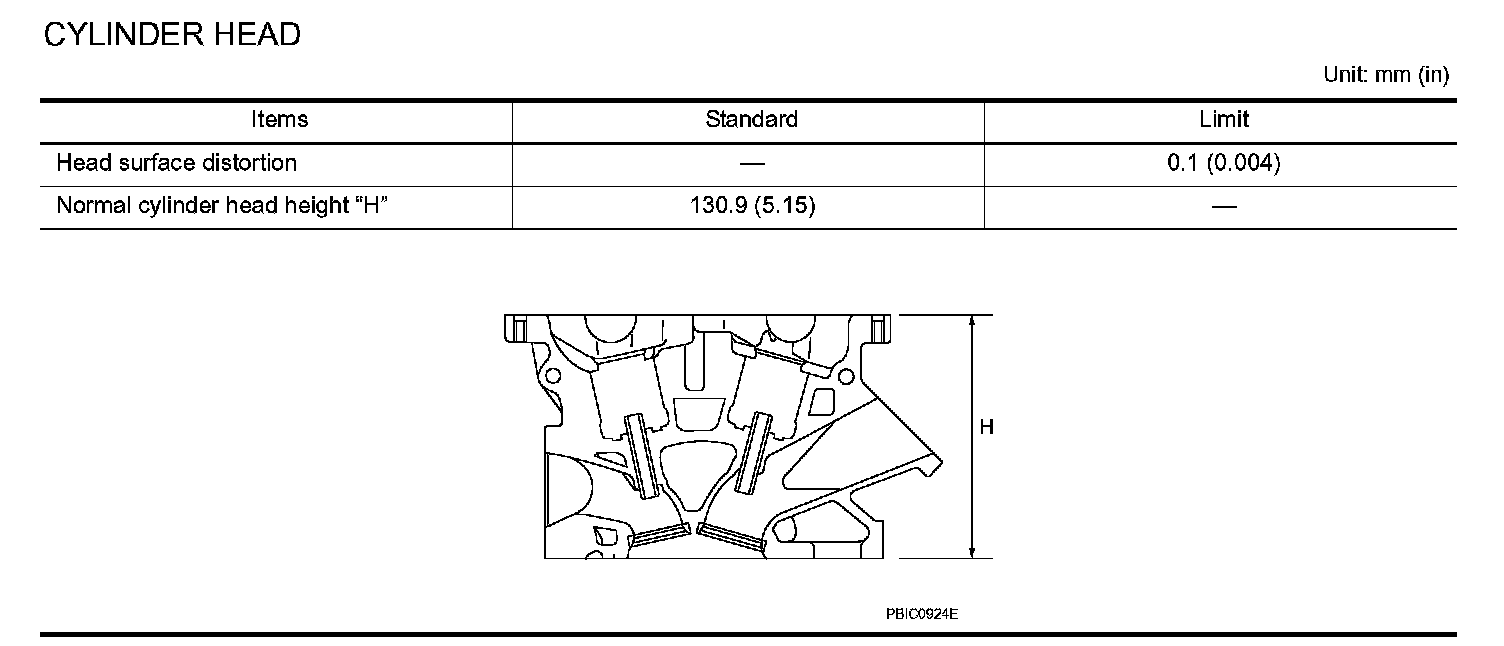
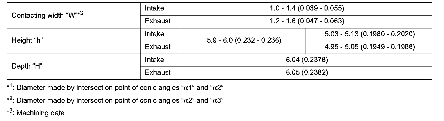
Cylinder Head
CYLINDER HEAD
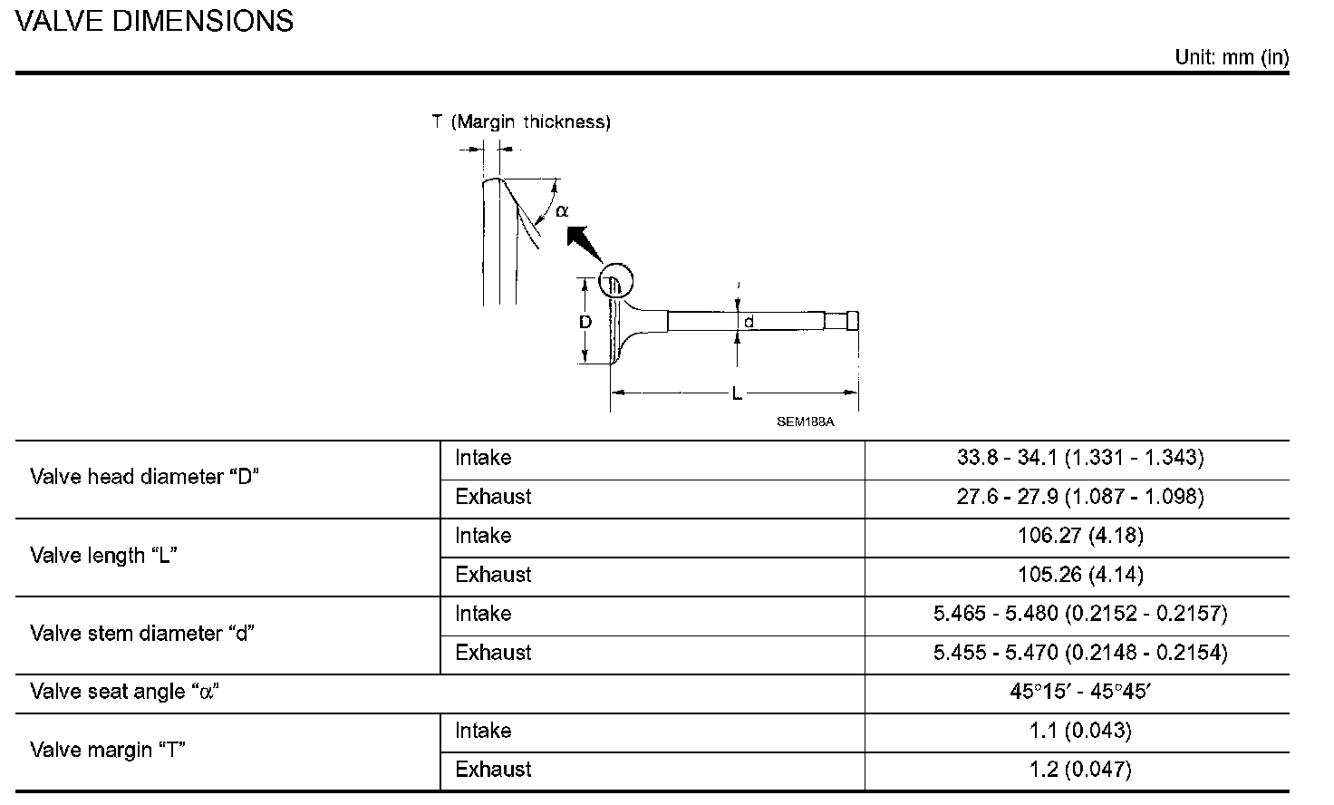
VALVE DIMENSIONS
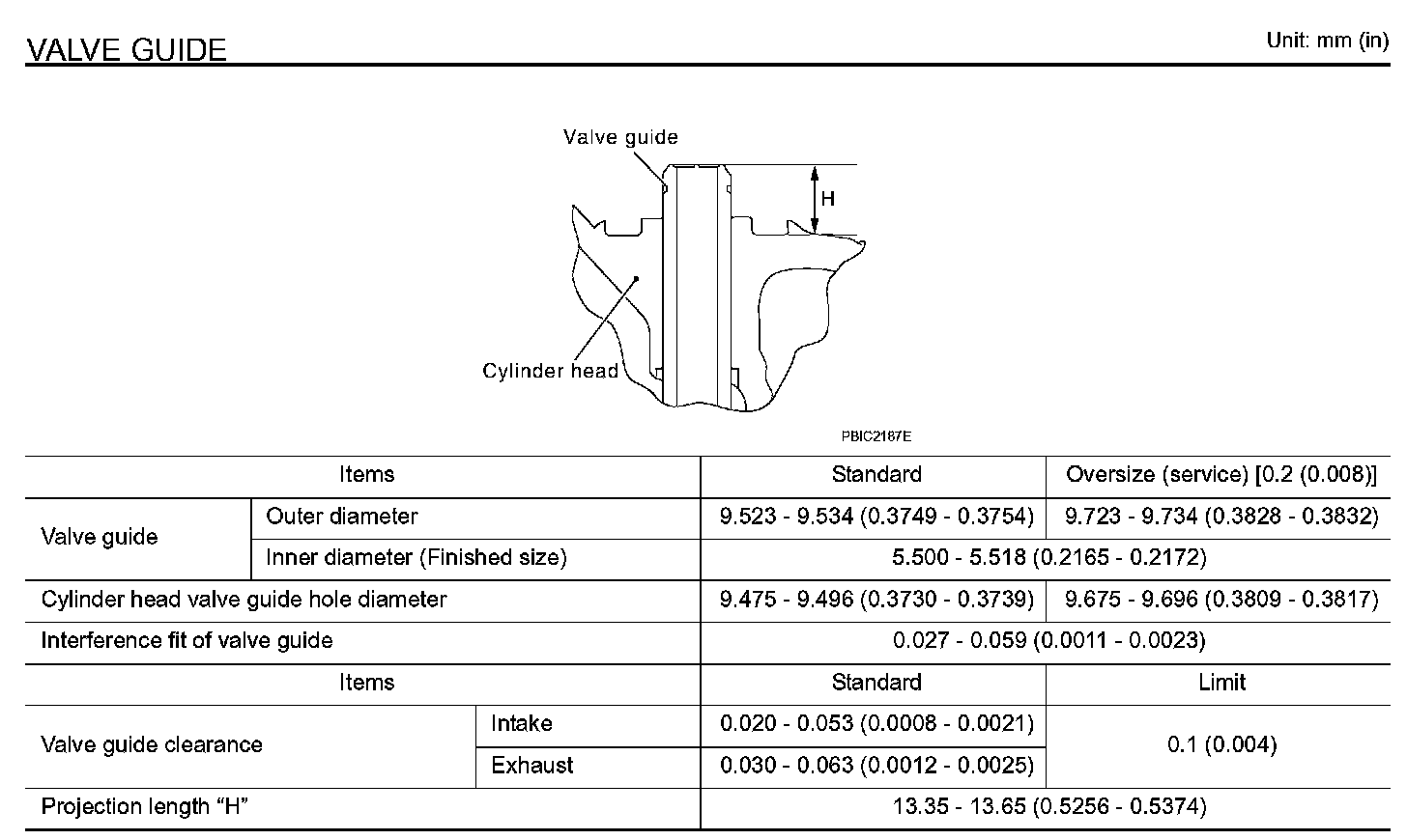
VALVE GUIDE
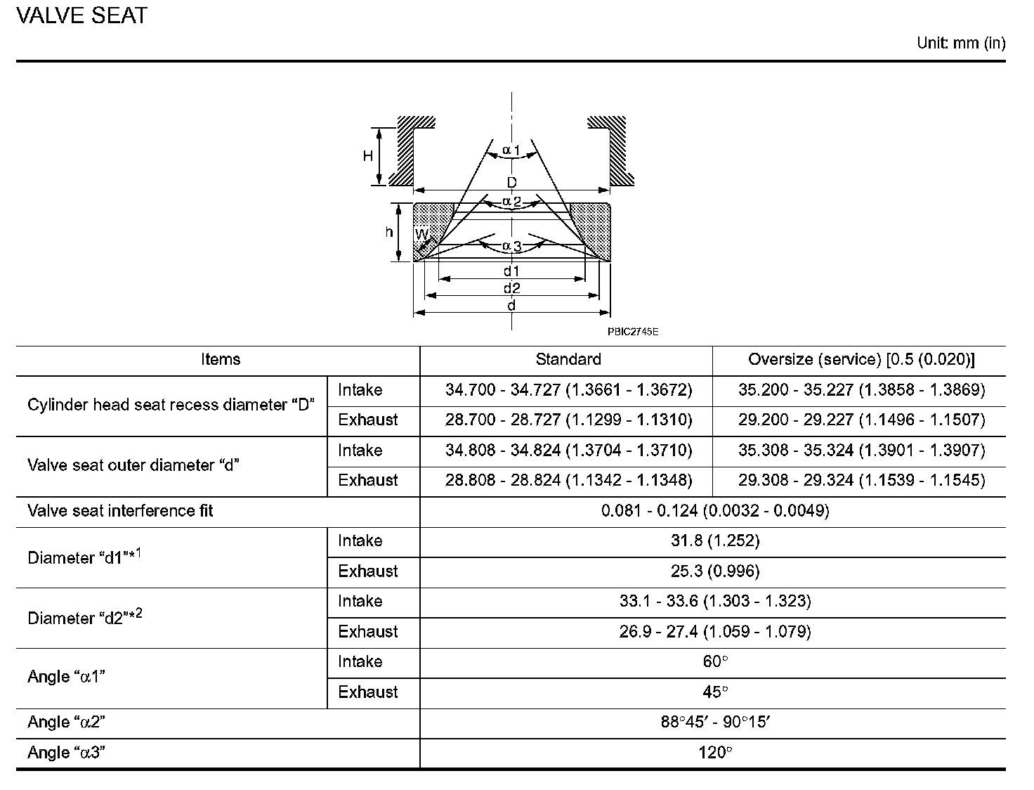
VALVE SEAT
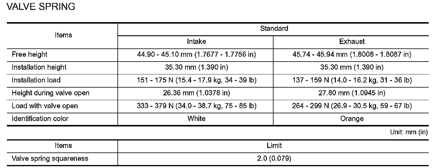
VALVE SPRING
Cylinder Head
Removal and Replacement
Cylinder Head
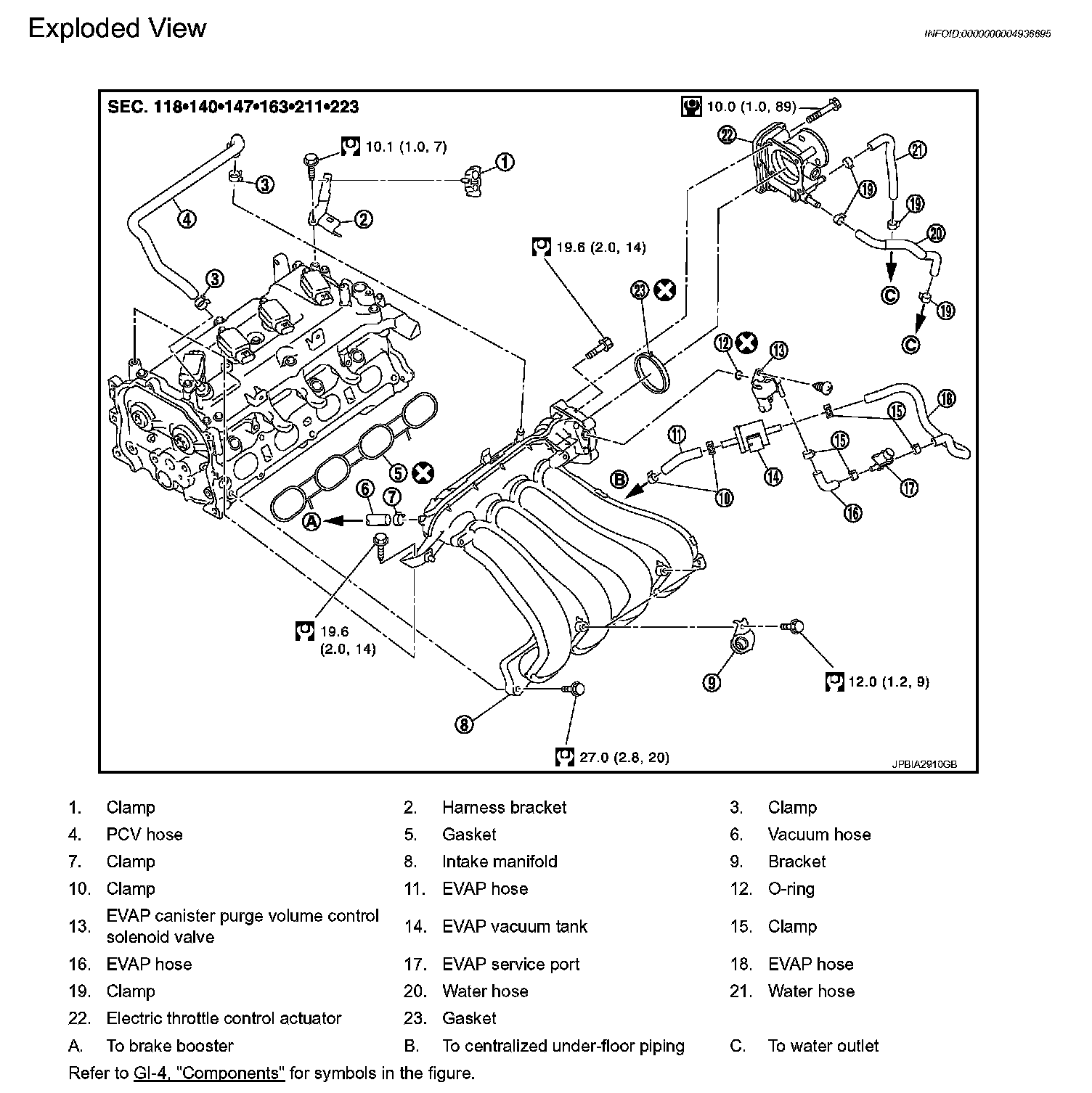
INTAKE MANIFOLD
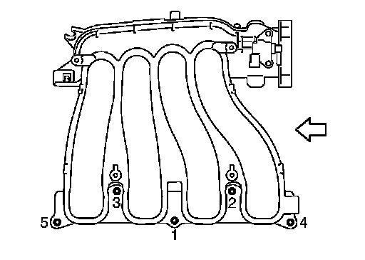
Tighten in numerical order as shown in the figure.
Tighten No. 1 bolt again.
Arrow Indicates Engine Front.
Camshaft Bearing Cap
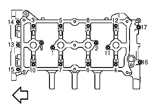
Tighten mounting bolts of camshaft brackets in the following steps, in numerical order as shown in the figure.
Arrow Indicates Engine Front.
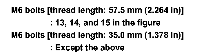
There are two types of mounting bolts. Refer to the following for locating bolts.
i. Tighten mounting bolts in numerical order.
Torque: 1.96 N.m (0.20 kg-m, 17 in-lb)
ii. Tighten mounting bolts in numerical order.
Torque: 5.88 N.m (0.60 kg-m, 52 in-lb)
iii. Tighten mounting bolts in numerical order.
Torque: 9.5 N.m (0.97 kg-m, 84 in-lb)
CAUTION: After tightening mounting bolts of camshaft brackets, be sure to wipe off excessive liquid gasket from the mating surface of cylinder head.
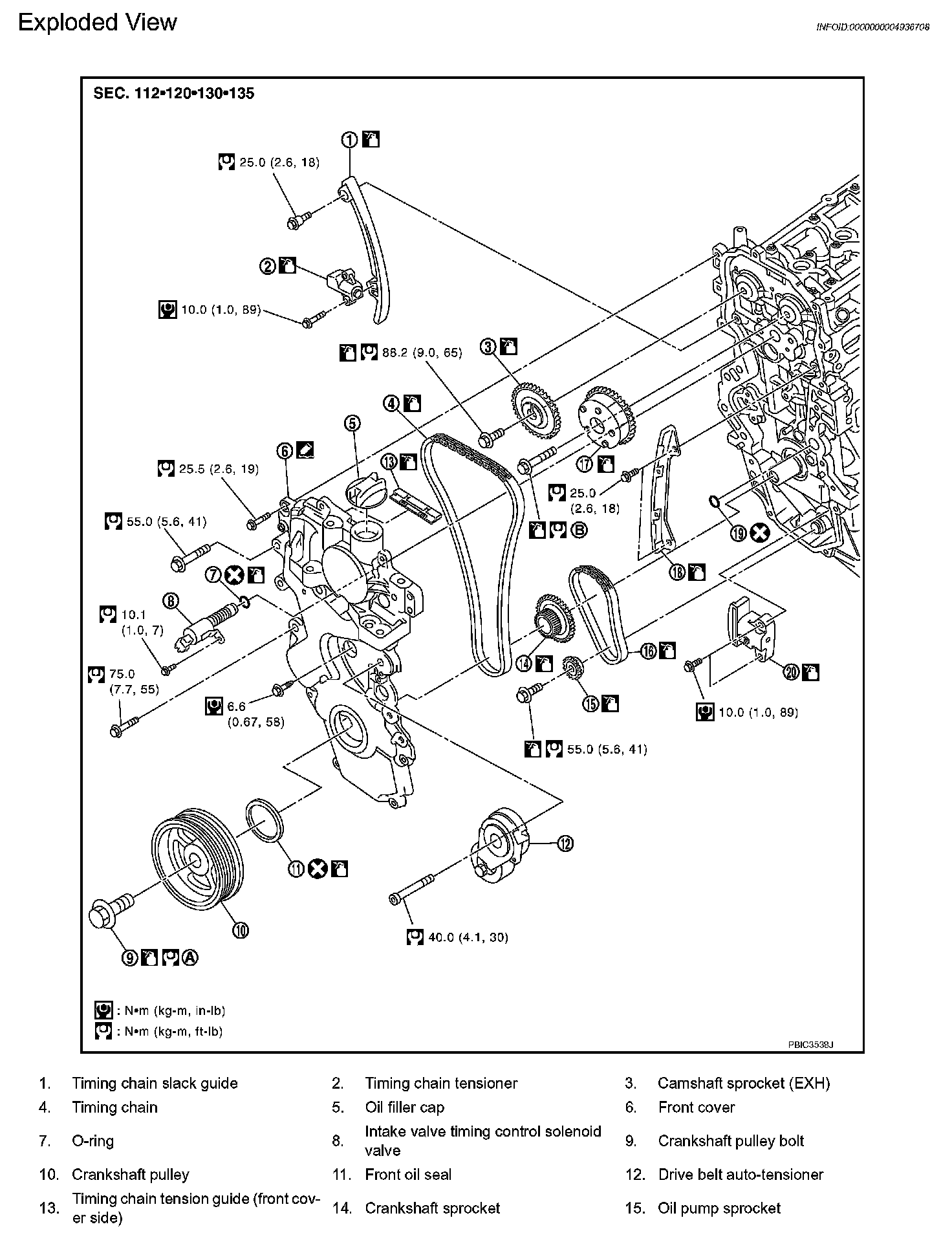
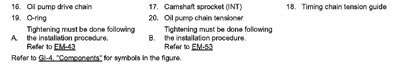
Camshaft Sprocket
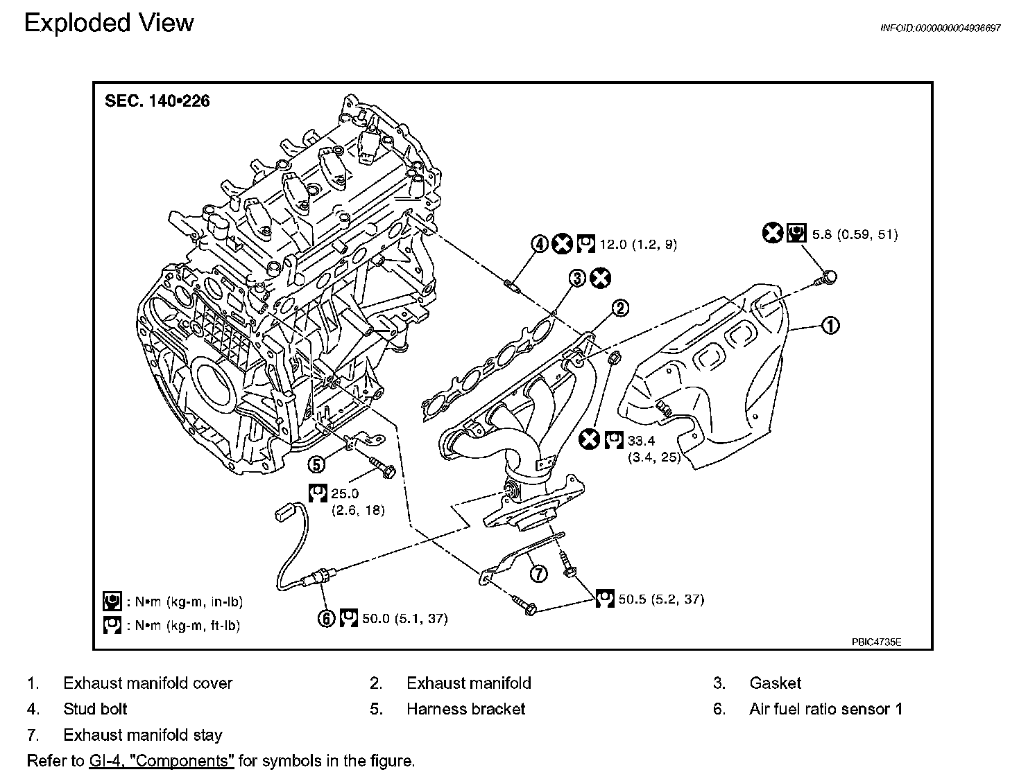
EXHAUST MANIFOLD
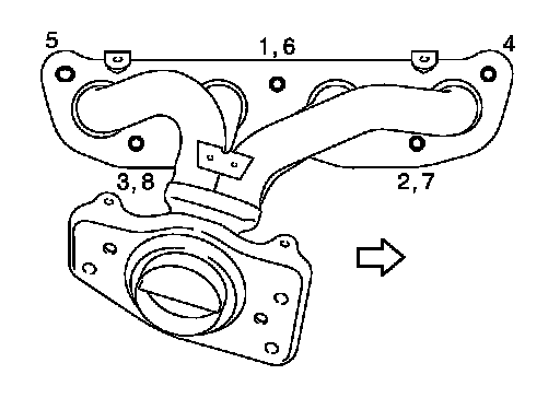
Tighten nuts in numerical order as shown in the figure.
NOTE:
No. 6 to 8 mean double tightening of nuts No. 1 to 3.
Arrow Indicates Engine Front.