Part 1
Communications Network
Pinpoint Tests
Pinpoint Test S: No Medium Speed Controller Area Network (MS-CAN) Communication, All Modules Are Not Responding
Refer to Wiring Diagram Set 14, Module Communications Network for schematic and connector information. Diagrams By Number
Normal Operation
The Medium Speed Controller Area Network (MS-CAN) uses an unshielded twisted pair cable which provide the network connection to all modules on the network.
This pinpoint test is intended to diagnose the following:
- Wiring, terminals or connectors
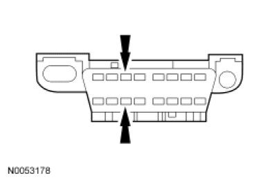
- Data Link Connector (DLC)
- Accessory Protocol Interface Module (APIM) (if equipped)
- Audio Control Module (ACM)
- Driver Seat Module (DSM) (if equipped)
- Global Positioning System Module (GPSM) (if equipped)
- HVAC module (if equipped)
- Instrument Cluster (IC)
- Parking Aid Module (PAM) (if equipped)
- Power Running Board (PRB) module (if equipped)
- Rear Entertainment Module (RETM) (if equipped)
- Satellite Digital Audio Receiver System (SDARS) module (if equipped)
- Smart Junction Box (SJB)
PINPOINT TEST S: NO MS-CAN COMMUNICATION, ALL MODULES ARE NOT RESPONDING
NOTICE: Use the correct probe adapter(s) when making measurements. Failure to use the correct probe adapter(s) may damage the connector.
NOTE: Most faults are due to connector and/or wiring concerns. Carry out a thorough inspection and verification before proceeding with the pinpoint test. Inspection and Verification
NOTE: Failure to disconnect the battery when instructed will result in false resistance readings. Refer to Battery.
-------------------------------------------------
S1 CHECK THE DLC PINS FOR DAMAGE
- Ignition OFF.
- Disconnect the scan tool cable from the DLC.
- Inspect DLC pins 3 and 11 for damage.
- Are DLC pins 3 and 11 OK?
Yes
GO to S2.
No
REPAIR the DLC as necessary. CLEAR the DTCs. REPEAT the network test with the scan tool.
-------------------------------------------------
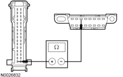
S2 CHECK THE MS-CAN TERMINATION RESISTANCE
- Disconnect: Negative Battery Cable.
- Measure the resistance between the DLC C251-3, circuit VDB06 (GY/OG), harness side and the DLC C251-11, circuit VDB07 (VT/OG), harness side.
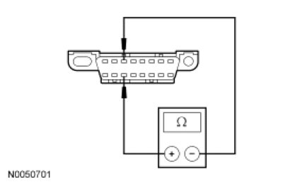
- Is the resistance between 54 and 66 ohms?
Yes
GO to S3.
No
GO to S5.
-------------------------------------------------
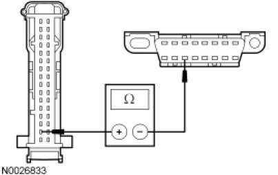
S3 CHECK THE MS-CAN (+) AND MS-CAN (-) CIRCUITS FOR A SHORT TO GROUND
- Measure the resistance between the DLC C251-3, circuit VDB06 (GY/OG), harness side and ground; and between the DLC C251-11, circuit VDB07 (VT/OG), harness side and ground.
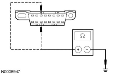
- Are the resistances greater than 1,000 ohms?
Yes
GO to S4.
No
GO to S30.
-------------------------------------------------
S4 CHECK THE MS-CAN (+) AND MS-CAN (-) CIRCUITS FOR A SHORT TO VOLTAGE
- Connect: Negative Battery Cable.
- Ignition ON.
- Measure the voltage between the DLC C251-3, circuit VDB06 (GY/OG), harness side and ground; and between the DLC C251-11, circuit VDB07 (VT/OG), harness side and ground.
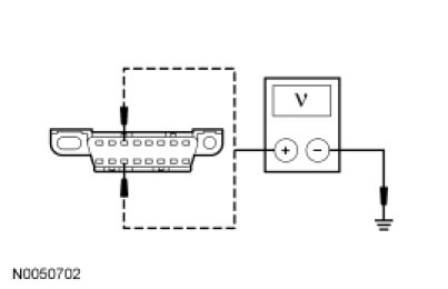
- Is the voltage greater than 6 volts?
Yes
REPAIR the circuit. CLEAR the DTCs. REPEAT the network test with the scan tool.
No
The CAN has tested within specifications. GO to Pinpoint Test R to diagnose the intermittent MS-CAN fault. Pinpoint Test R: Intermittent No Medium Speed Controller Area Network (MS-CAN) Communication, One Or More Modules Are Not Respo
-------------------------------------------------
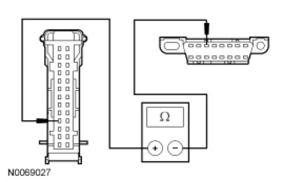
S5 CHECK THE MS-CAN TERMINATION RESISTOR
- Measure the resistance between the DLC C251-3, circuit VDB06 (GY/OG), harness side and the DLC C251-11, circuit VDB07 (VT/OG), harness side.
- Is the resistance between 108 and 132 ohms?
Yes
GO to S6.
No
GO to S9.
-------------------------------------------------
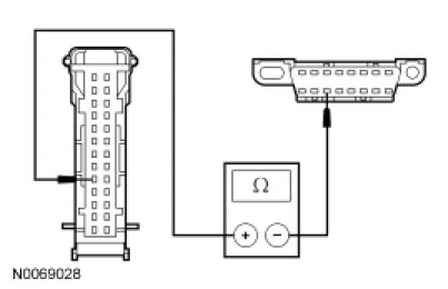
S6 CHECK THE MS-CAN TERMINATION RESISTOR WITH THE SJB DISCONNECTED
- Disconnect: SJB C2280b.
- Measure the resistance between the DLC C251-3, circuit VDB06 (GY/OG), harness side and the DLC C251-11, circuit VDB07 (VT/OG), harness side.
- Is the resistance between 108 and 132 ohms?
Yes
GO to S7.
No
GO to S8.
-------------------------------------------------
S7 CHECK THE MS-CAN CIRCUITS BETWEEN THE SJB AND THE DLC FOR AN OPEN
- Measure the resistance between the SJB C2280d-16, circuit VDB06 (GY/OG), harness side and the DLC C251-3, circuit VDB06 (GY/OG), harness side.
- Measure the resistance between the SJB C2280d-15, circuit VDB07 (VT/OG), harness side and the DLC C251-11, circuit VDB07 (VT/OG), harness side.
- Are the resistances less than 5 ohms?
Yes
CONNECT the negative battery cable. GO to S59.
No
REPAIR the circuit in question. CONNECT the negative battery cable. CLEAR the DTCs. REPEAT the network test with the scan tool.
-------------------------------------------------
S8 CHECK THE MS-CAN CIRCUITS BETWEEN THE IC AND THE DLC FOR AN OPEN
- Disconnect: IC C220.
- Measure the resistance between the IC C220-4, circuit VDB06 (GY/OG), harness side and the DLC C251-3, circuit VDB06 (GY/OG), harness side.
- Measure the resistance between the IC C220-5, circuit VDB07 (VT/OG), harness side and the DLC C251-11, circuit VDB07 (VT/OG), harness side.
- Are the resistances less than 5 ohms?
Yes
CONNECT the negative battery cable. GO to S49.
No
REPAIR the circuit in question. CONNECT the negative battery cable. CLEAR the DTCs. REPEAT the network test with the scan tool.
-------------------------------------------------
S9 CHECK THE MS-CAN (+) AND MS-CAN (-) CIRCUITS FOR A SHORT TOGETHER
- Measure the resistance between the DLC C251-3, circuit VDB06 (GY/OG), harness side and the DLC C251-11, circuit VDB07 (VT/OG), harness side.
- Is the resistance less than 5 ohms?
Yes
GO to S11.
No
GO to S10.
-------------------------------------------------
S10 CHECK THE MS-CAN (+) AND MS-CAN (-) CIRCUITS FOR AN OPEN
- Measure the resistance between the DLC C251-3, circuit VDB06 (GY/OG), harness side and the DLC C251-11, circuit VDB07 (VT/OG), harness side.
- Is the resistance greater than 10,000 ohms?
Yes
REPAIR the DLC or REPAIR the circuit in question. CONNECT the negative battery cable. VERIFY the scan tool operation on a substitute vehicle. CLEAR the DTCs. REPEAT the network test on the suspect vehicle.
No
A capacitor internal to a module may still be draining causing irregular resistance readings. WAIT 5 minutes. REPEAT the pinpoint test.
-------------------------------------------------
S11 CHECK THE MS-CAN (+) AND MS-CAN (-) CIRCUITS FOR A SHORT TOGETHER WITH THE IC DISCONNECTED
- Disconnect: IC C220.
- Measure the resistance between the DLC C251-3, circuit VDB06 (GY/OG), harness side and the DLC C251-11, circuit VDB07 (VT/OG), harness side.
- Is the resistance less than 5 ohms?
Yes
GO to S12.
No
CONNECT the negative battery cable. GO to S49.
-------------------------------------------------
S12 CHECK THE MS-CAN (+) AND MS-CAN (-) CIRCUITS FOR A SHORT TOGETHER WITH THE ACM DISCONNECTED
- Disconnect: ACM C290b.
- Measure the resistance between the DLC C251-3, circuit VDB06 (GY/OG), harness side and the DLC C251-11, circuit VDB07 (VT/OG), harness side.
- Is the resistance less than 5 ohms?
Yes
GO to S13.
No
CONNECT the negative battery cable. GO to S50.
-------------------------------------------------
S13 VERIFY VEHICLE EQUIPMENT - HVAC MODULE
- Inspect the vehicle for an HVAC module.
- Is the vehicle equipped with an HVAC module?
Yes
GO to S14.
No
GO to S15.
-------------------------------------------------
S14 CHECK THE MS-CAN (+) AND MS-CAN (-) CIRCUITS FOR A SHORT TOGETHER WITH THE HVAC MODULE DISCONNECTED
- Disconnect: HVAC Module C228a.
- Measure the resistance between the DLC C251-3, circuit VDB06 (GY/OG), harness side and the DLC C251-11, circuit VDB07 (VT/OG), harness side.
- Is the resistance less than 5 ohms?
Yes
GO to S15.
No
CONNECT the negative battery cable. GO to S51.
-------------------------------------------------
S15 VERIFY VEHICLE EQUIPMENT - RETM
- Inspect the vehicle for an RETM.
- Is the vehicle equipped with an RETM?
Yes
GO to S16.
No
GO to S17.
-------------------------------------------------
S16 CHECK THE MS-CAN (+) AND MS-CAN (-) CIRCUITS FOR A SHORT TOGETHER WITH THE RETM DISCONNECTED
- Disconnect: RETM C9029.
- Measure the resistance between the DLC C251-3, circuit VDB06 (GY/OG), harness side and the DLC C251-11, circuit VDB07 (VT/OG), harness side.
- Is the resistance less than 5 ohms?
Yes
GO to S17.
No
CONNECT the negative battery cable. GO to S52.
-------------------------------------------------
S17 VERIFY VEHICLE EQUIPMENT - DSM
- Inspect the vehicle for a DSM.
- Is the vehicle equipped with a DSM?
Yes
GO to S18.
No
GO to S19.
-------------------------------------------------
S18 CHECK THE MS-CAN (+) AND MS-CAN (-) CIRCUITS FOR A SHORT TOGETHER WITH THE DSM DISCONNECTED
- Disconnect: DSM C341c.
- Measure the resistance between the DLC C251-3, circuit VDB06 (GY/OG), harness side and the DLC C251-11, circuit VDB07 (VT/OG), harness side.
- Is the resistance less than 5 ohms?
Yes
GO to S19.
No
CONNECT the negative battery cable. GO to S53.
-------------------------------------------------
S19 VERIFY VEHICLE EQUIPMENT - SDARS MODULE
- Inspect the vehicle for a SDARS module.
- Is the vehicle equipped with a SDARS module?
Yes
GO to S20.
No
GO to S21.
-------------------------------------------------
S20 CHECK THE MS-CAN (+) AND MS-CAN (-) CIRCUITS FOR A SHORT TOGETHER WITH THE SDARS MODULE DISCONNECTED
- Disconnect: SDARS C3290.
- Measure the resistance between the DLC C251-3, circuit VDB06 (GY/OG), harness side and the DLC C251-11, circuit VDB07 (VT/OG), harness side.
- Is the resistance less than 5 ohms?
Yes
GO to S21.
No
CONNECT the negative battery cable. GO to S54.
-------------------------------------------------
S21 VERIFY VEHICLE EQUIPMENT - PRB MODULE
- Inspect the vehicle for a PRB module.
- Is the vehicle equipped with a PRB module?
Yes
GO to S22.
No
GO to S23.
-------------------------------------------------
S22 CHECK THE MS-CAN (+) AND MS-CAN (-) CIRCUITS FOR A SHORT TOGETHER WITH THE PRB MODULE DISCONNECTED
- Disconnect: PRB Module C4322b.
- Measure the resistance between the DLC C251-3, circuit VDB06 (GY/OG), harness side and the DLC C251-11, circuit VDB07 (VT/OG), harness side.
- Is the resistance less than 5 ohms?
Yes
GO to S23.
No
CONNECT the negative battery cable. GO to S55.
-------------------------------------------------
S23 VERIFY VEHICLE EQUIPMENT - PAM
- Inspect the vehicle for a PAM.
- Is the vehicle equipped with a PAM?
Yes
GO to S24.
No
GO to S25.
-------------------------------------------------
S24 CHECK THE MS-CAN (+) AND MS-CAN (-) CIRCUITS FOR A SHORT TOGETHER WITH THE PAM DISCONNECTED
- Disconnect: PAM C4014 (Mountaineer), C3267 (Explorer Sport Trac) or C4226 (Explorer).
- Measure the resistance between the DLC C251-3, circuit VDB06 (GY/OG), harness side and the DLC C251-11, circuit VDB07 (VT/OG), harness side.
- Is the resistance less than 5 ohms?
Yes
GO to S25.
No
CONNECT the negative battery cable. GO to S56.
-------------------------------------------------
S25 VERIFY VEHICLE EQUIPMENT - APIM
- Inspect the vehicle for an APIM.
- Is the vehicle equipped with an APIM?
Yes
GO to S26.
No
GO to S27.
-------------------------------------------------
S26 CHECK THE MS-CAN (+) AND MS-CAN (-) CIRCUITS FOR A SHORT TOGETHER WITH THE APIM DISCONNECTED
- Disconnect: APIM C3342.
- Measure the resistance between the DLC C251-3, circuit VDB06 (GY/OG), harness side and the DLC C251-11, circuit VDB07 (VT/OG), harness side.
- Is the resistance less than 5 ohms?
Yes
GO to S27.
No
CONNECT the negative battery cable.GO to S57.
-------------------------------------------------
S27 VERIFY VEHICLE EQUIPMENT - GPSM
- Inspect the vehicle for a Global Positioning System Module (GPSM).
- Is the vehicle equipped with a GPSM?
Yes
GO to S28.
No
GO to S29.
-------------------------------------------------
S28 CHECK THE MS-CAN (+) AND MS-CAN (-) CIRCUITS FOR A SHORT TOGETHER WITH THE GPSM DISCONNECTED
- Disconnect: GPSM C2398.
- Measure the resistance between the DLC C251-3, circuit VDB06 (GY/OG), harness side and the DLC C251-11, circuit VDB07 (VT/OG), harness side.
- Is the resistance less than 5 ohms?
Yes
GO to S29.
No
CONNECT the negative battery cable.GO to S58.
-------------------------------------------------
S29 CHECK THE MS-CAN (+) AND MS-CAN (-) CIRCUITS FOR A SHORT TOGETHER WITH THE SJB DISCONNECTED
- Disconnect: SJB C2280d.
- Measure the resistance between the DLC C251-3, circuit VDB06 (GY/OG), harness side and the DLC C251-11, circuit VDB07 (VT/OG), harness side.
- Is the resistance less than 5 ohms?
Yes
REPAIR the circuit in question. CONNECT all modules. CONNECT the negative battery cable. CLEAR the DTCs. REPEAT the network test with the scan tool.
No
CONNECT the negative battery cable. GO to S59.
-------------------------------------------------
S30 CHECK THE MS-CAN (+) AND MS-CAN (-) CIRCUITS FOR A SHORT TO GROUND WITH THE IC DISCONNECTED
- Disconnect: IC C220.
- Measure the resistance between the DLC C251-3, circuit VDB06 (GY/OG), harness side and ground; and between the DLC C251-11, circuit VDB07 (VT/OG), harness side and ground.
- Are the resistances greater than 1,000 ohms?
Yes
CONNECT the negative battery cable. GO to S49.
No
GO to S31.
-------------------------------------------------