Q28-Q54
Communications Network
Pinpoint Tests
Pinpoint Test Q: No Medium Speed Controller Area Network (MS-CAN) Communication, All Modules Are Not Responding
Refer to Wiring Diagram Set 14, Module Communications Network for schematic and connector information. Diagrams By Number
Normal Operation
The Medium Speed Controller Area Network (MS-CAN) uses an unshielded twisted pair cable, circuits VDB06 (GY/OG) and VDB07 (VT/OG) provide the network connection to all modules on the network.
This pinpoint test is intended to diagnose the following:
- Wiring, terminals or connectors
- Accessory Protocol Interface Module (APIM) (if equipped)
- Audio Control Module (ACM)
- Driver Seat Module (DSM) (if equipped)
- HVAC module (if equipped)
- Instrument Cluster (IC)
- Parking Aid Module (PAM) (if equipped)
- Power Running Board (PRB) module (if equipped)
- Rear Entertainment Module (RETM) (if equipped)
- Satellite Digital Audio Receiver System (SDARS) module (if equipped)
- Smart Junction Box (SJB)
PINPOINT TEST Q: NO MS-CAN COMMUNICATION, ALL MODULES ARE NOT RESPONDING
NOTICE: Use the correct probe adapter(s) when making measurements. Failure to use the correct probe adapter(s) may damage the connector.
NOTE: Most faults are due to connector and/or wiring concerns. Carry out a thorough inspection and verification before proceeding with the pinpoint test. Inspection and Verification
NOTE: Failure to disconnect the battery when instructed will result in false resistance readings. Refer to Battery.
-------------------------------------------------
Q28 CHECK THE MS-CAN (+) AND MS-CAN (-) CIRCUITS FOR A SHORT TO GROUND WITH THE IC DISCONNECTED
- Disconnect: ICC220.
- Measure the resistance between the DLC C251-3, circuit VDB06 (GY/OG), harness side and ground; and between the DLC C251-11, circuit VDB07 (VT/OG), harness side and ground.
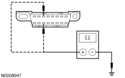
- Are the resistances greater than 1,000 ohms?
Yes
CONNECT the negative battery cable. GO to Q45.
No
GO to Q29.
-------------------------------------------------
Q29 CHECK THE MS-CAN (+) AND MS-CAN (-) CIRCUITS FOR A SHORT TO GROUND WITH THE ACM DISCONNECTED
- Disconnect: ACM C290b.
- Measure the resistance between the DLC C251-3, circuit VDB06 (GY/OG), harness side and ground; and between the DLC C251-11, circuit VDB07 (VT/OG), harness side and ground.
- Are the resistances greater than 1,000 ohms?
Yes
CONNECT the negative battery cable. GO to Q46.
No
GO to Q30.
-------------------------------------------------
Q30 VERIFY VEHICLE EQUIPMENT - HVAC MODULE
- Inspect the vehicle for an HVAC module.
- Is the vehicle equipped with an HVAC module?
Yes
GO to Q31.
No
GO to Q32.
-------------------------------------------------
Q31 CHECK THE MS-CAN (+) AND MS-CAN (-) CIRCUITS FOR A SHORT TO GROUND WITH THE HVAC MODULE DISCONNECTED
- Disconnect: HVAC Module C228a.
- Measure the resistance between the DLC C251-3, circuit VDB06 (GY/OG), harness side and ground; and between the DLC C251-11, circuit VDB07 (VT/OG), harness side and ground.
- Are the resistances greater than 1,000 ohms?
Yes
CONNECT the negative battery cable. GO to Q47.
No
GO to Q32.
-------------------------------------------------
Q32 VERIFY VEHICLE EQUIPMENT - RETM
- Inspect the vehicle for a RETM.
- Is the vehicle equipped with a RETM?
Yes
GO to Q33.
No
GO to Q34.
-------------------------------------------------
Q33 CHECK THE MS-CAN (+) AND MS-CAN (-) CIRCUITS FOR A SHORT TO GROUND WITH THE RETM DISCONNECTED
- Disconnect: RETM C9029.
- Measure the resistance between the DLC C251-3, circuit VDB06 (GY/OG), harness side and ground; and between the DLC C251-11, circuit VDB07 (VT/OG), harness side and ground.
- Are the resistances greater than 1,000 ohms?
Yes
CONNECT the negative battery cable. GO to Q48.
No
GO to Q34.
-------------------------------------------------
Q34 VERIFY VEHICLE EQUIPMENT - DSM
- Inspect the vehicle for a DSM.
- Is the vehicle equipped with a DSM?
Yes
GO to Q35.
No
GO to Q36.
-------------------------------------------------
Q35 CHECK THE MS-CAN (+) AND MS-CAN (-) CIRCUITS FOR A SHORT TO GROUND WITH THE DSM DISCONNECTED
- Disconnect: DSM C341c.
- Measure the resistance between the DLC C251-3, circuit VDB06 (GY/OG), harness side and ground; and between the DLC C251-11, circuit VDB07 (VT/OG), harness side and ground.
- Are the resistances greater than 1,000 ohms?
Yes
CONNECT the negative battery cable. GO to Q49.
No
GO to Q36.
-------------------------------------------------
Q36 VERIFY VEHICLE EQUIPMENT - SDARS MODULE
- Inspect the vehicle for a SDARS module.
- Is the vehicle equipped with a SDARS module?
Yes
GO to Q37.
No
GO to Q38.
-------------------------------------------------
Q37 CHECK THE MS-CAN (+) AND MS-CAN (-) CIRCUITS FOR A SHORT TO GROUND WITH THE SDARS MODULE DISCONNECTED
- Disconnect: SDARS Module C3290.
- Measure the resistance between the DLC C251-3, circuit VDB06 (GY/OG), harness side and ground; and between the DLC C251-11, circuit VDB07 (VT/OG), harness side and ground.
- Are the resistances greater than 1,000 ohms?
Yes
CONNECT the negative battery cable. GO to Q50.
No
GO to Q38.
-------------------------------------------------
Q38 VERIFY VEHICLE EQUIPMENT - PRB MODULE
- Inspect the vehicle for a PRB module.
- Is the vehicle equipped with a PRB module?
Yes
GO to Q39.
No
GO to Q40.
-------------------------------------------------
Q39 CHECK THE MS-CAN (+) AND MS-CAN (-) CIRCUITS FOR A SHORT TO GROUND WITH THE PRB MODULE DISCONNECTED
- Disconnect: PRB Module C4322b.
- Measure the resistance between the DLC C251-3, circuit VDB06 (GY/OG), harness side and ground; and between the DLC C251-11, circuit VDB07 (VT/OG), harness side and ground.
- Are the resistances greater than 1,000 ohms?
Yes
CONNECT the negative battery cable. GO to Q51.
No
GO to Q40.
-------------------------------------------------
Q40 VERIFY VEHICLE EQUIPMENT - PAM
- Inspect the vehicle for a PAM.
- Is the vehicle equipped with a PAM?
Yes
GO to Q41.
No
GO to Q42.
-------------------------------------------------
Q41 CHECK THE MS-CAN (+) AND MS-CAN (-) CIRCUITS FOR A SHORT TO GROUND WITH THE PAM DISCONNECTED
- Disconnect: PAM C4014 (Mountaineer), C3267 (Explorer Sport Trac) or C4226 (Explorer).
- Measure the resistance between the DLC C251-3, circuit VDB06 (GY/OG), harness side and ground; and between the DLC C251-11, circuit VDB07 (VT/OG), harness side and ground.
- Are the resistances greater than 1,000 ohms?
Yes
CONNECT the negative battery cable. GO to Q52.
No
GO to Q42.
-------------------------------------------------
Q42 VERIFY VEHICLE EQUIPMENT - APIM
- Inspect the vehicle for an APIM.
- Is the vehicle equipped with an APIM?
Yes
GO to Q43.
No
GO to Q44.
-------------------------------------------------
Q43 CHECK THE MS-CAN (+) AND MS-CAN (-) CIRCUITS FOR A SHORT TO GROUND WITH THE APIM DISCONNECTED
- Disconnect: APIM C3342.
- Measure the resistance between the DLC C251-3, circuit VDB06 (GY/OG), harness side and ground; and between the DLC C251-11, circuit VDB07 (VT/OG), harness side and ground.
- Are the resistances greater than 1,000 ohms?
Yes
CONNECT the negative battery cable. GO to Q53.
No
GO to Q44.
-------------------------------------------------
Q44 CHECK THE MS-CAN (+) AND MS-CAN (-) CIRCUITS FOR A SHORT TO GROUND WITH THE SJB DISCONNECTED
- Disconnect: SJB C2280d.
- Measure the resistance between the DLC C251-3, circuit VDB06 (GY/OG), harness side and ground; and between the DLC C251-11, circuit VDB07 (VT/OG), harness side and ground.
- Are the resistances greater than 1,000 ohms?
Yes
CONNECT the negative battery cable. GO to Q54.
No
REPAIR the circuit in question. CONNECT all modules. CONNECT the negative battery cable. CLEAR the DTCs. REPEAT the network test with the scan tool.
-------------------------------------------------
Q45 CHECK FOR CORRECT IC OPERATION
- Disconnect the IC connector.
- Check for:
- corrosion
- damaged pins
- pushed-out pins
- Connect the IC connector and make sure it seats correctly.
- Operate the system and verify the concern is still present.
- Is the concern still present?
Yes
INSTALL a new IC. CONNECT all modules. CLEAR the DTCs. REPEAT the network test with the scan tool.
No
The system is operating correctly at this time. The concern may have been caused by a loose or corroded connector. CONNECT all modules. CLEAR the DTCs. REPEAT the network test with the scan tool.
-------------------------------------------------
Q46 CHECK FOR CORRECT ACM OPERATION
- Disconnect all the ACM connectors.
- Check for:
- corrosion
- damaged pins
- pushed-out pins
- Connect all the ACM connectors and make sure they seat correctly.
- Operate the system and verify the concern is still present.
- Is the concern still present?
Yes
INSTALL a new ACM. CONNECT all modules. CLEAR the DTCs. REPEAT the network test with the scan tool.
No
The system is operating correctly at this time. The concern may have been caused by a loose or corroded connector. CONNECT all modules. CLEAR the DTCs. REPEAT the network test with the scan tool.
-------------------------------------------------
Q47 CHECK FOR CORRECT HVAC MODULE OPERATION
- Disconnect all the HVAC module connectors.
- Check for:
- corrosion
- damaged pins
- pushed-out pins
- Connect all the HVAC module connectors and make sure they seat correctly.
- Operate the system and verify the concern is still present.
- Is the concern still present?
Yes
INSTALL a new HVAC module. CONNECT all modules. CLEAR the DTCs. REPEAT the network test with the scan tool.
No
The system is operating correctly at this time. The concern may have been caused by a loose or corroded connector. CONNECT all modules. CLEAR the DTCs. REPEAT the network test with the scan tool.
-------------------------------------------------
Q48 CHECK FOR CORRECT RETM OPERATION
- Disconnect the RETM connector.
- Check for:
- corrosion
- damaged pins
- pushed-out pins
- Connect the RETM connector and make sure it seats correctly.
- Operate the system and verify the concern is still present.
- Is the concern still present?
Yes
INSTALL a new RETM. CONNECT all modules. CLEAR the DTCs. REPEAT the network test with the scan tool.
No
The system is operating correctly at this time. The concern may have been caused by a loose or corroded connector. CONNECT all modules. CLEAR the DTCs. REPEAT the network test with the scan tool.
-------------------------------------------------
Q49 CHECK FOR CORRECT DSM OPERATION
- Disconnect all the DSM connectors.
- Check for:
- corrosion
- damaged pins
- pushed-out pins
- Connect all the DSM connectors and make sure they seat correctly.
- Operate the system and verify the concern is still present.
- Is the concern still present?
Yes
INSTALL a new DSM. CONNECT all modules. CLEAR the DTCs. REPEAT the network test with the scan tool.
No
The system is operating correctly at this time. The concern may have been caused by a loose or corroded connector. CONNECT all modules. CLEAR the DTCs. REPEAT the network test with the scan tool.
-------------------------------------------------
Q50 CHECK FOR CORRECT SDARS MODULE OPERATION
- Disconnect the SDARS module connector.
- Check for:
- corrosion
- damaged pins
- pushed-out pins
- Connect the SDARS module connector and make sure it seats correctly.
- Operate the system and verify the concern is still present.
- Is the concern still present?
Yes
INSTALL a new SDARS module. CONNECT all modules. CLEAR the DTCs. REPEAT the network test with the scan tool.
No
The system is operating correctly at this time. The concern may have been caused by a loose or corroded connector. CONNECT all modules. CLEAR the DTCs. REPEAT the network test with the scan tool.
-------------------------------------------------
Q51 CHECK FOR CORRECT PRB MODULE OPERATION
- Disconnect all the PRB module connectors.
- Check for:
- corrosion
- damaged pins
- pushed-out pins
- Connect all the PRB module connectors and make sure they seat correctly.
- Operate the system and verify the concern is still present.
- Is the concern still present?
Yes
INSTALL a new PRB module. CONNECT all modules. CLEAR the DTCs. REPEAT the network test with the scan tool.
No
The system is operating correctly at this time. The concern may have been caused by a loose or corroded connector. CONNECT all modules. CLEAR the DTCs. REPEAT the network test with the scan tool.
-------------------------------------------------
Q52 CHECK FOR CORRECT PAM OPERATION
- Disconnect the PAM connector.
- Check for:
- corrosion
- damaged pins
- pushed-out pins
- Connect the PAM connector and make sure it seats correctly.
- Operate the system and verify the concern is still present.
- Is the concern still present?
Yes
INSTALL a new PAM. CONNECT all modules. CLEAR the DTCs. REPEAT the network test with the scan tool.
No
The system is operating correctly at this time. The concern may have been caused by a loose or corroded connector. CONNECT all modules. CLEAR the DTCs. REPEAT the network test with the scan tool.
-------------------------------------------------
Q53 CHECK FOR CORRECT APIM OPERATION
- Disconnect the APIM connector.
- Check for:
- corrosion
- damaged pins
- pushed-out pins
- Connect the APIM connector and make sure it seats correctly.
- Operate the system and verify the concern is still present.
- Is the concern still present?
Yes
INSTALL a new APIM. CONNECT all modules. CLEAR the DTCs. REPEAT the network test with the scan tool.
No
The system is operating correctly at this time. The concern may have been caused by a loose or corroded connector. CONNECT all modules. CLEAR the DTCs. REPEAT the network test with the scan tool.
-------------------------------------------------
Q54 CHECK FOR CORRECT SJB OPERATION
- Disconnect all the SJB connectors.
- Check for:
- corrosion
- damaged pins
- pushed-out pins
- Connect all the SJB connectors and make sure they seat correctly.
- Operate the system and verify the concern is still present.
- Is the concern still present?
Yes
INSTALL a new SJB. CONNECT all modules. CLEAR the DTCs. REPEAT the network test with the scan tool.
No
The system is operating correctly at this time. The concern may have been caused by a loose or corroded connector. CONNECT all modules. CLEAR the DTCs. REPEAT the network test with the scan tool.
-------------------------------------------------