Pinpoint Test 3: Anti-Lock Brake System (ABS) Module Does Not Respond to the Diagnostic Tool
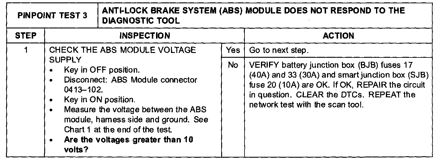
PINPOINT TEST 3: ANTI-LOCK BRAKE SYSTEM (ABS) MODULE DOES NOT RESPOND TO THE DIAGNOSTIC TOOLStep 1:
Step 2-Step 6:
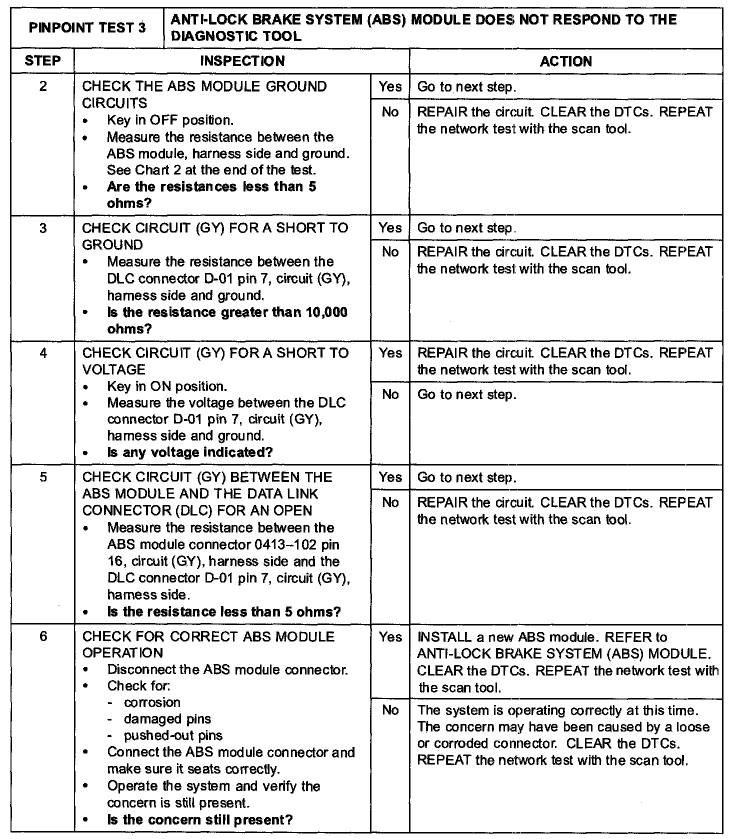
Chart 1:
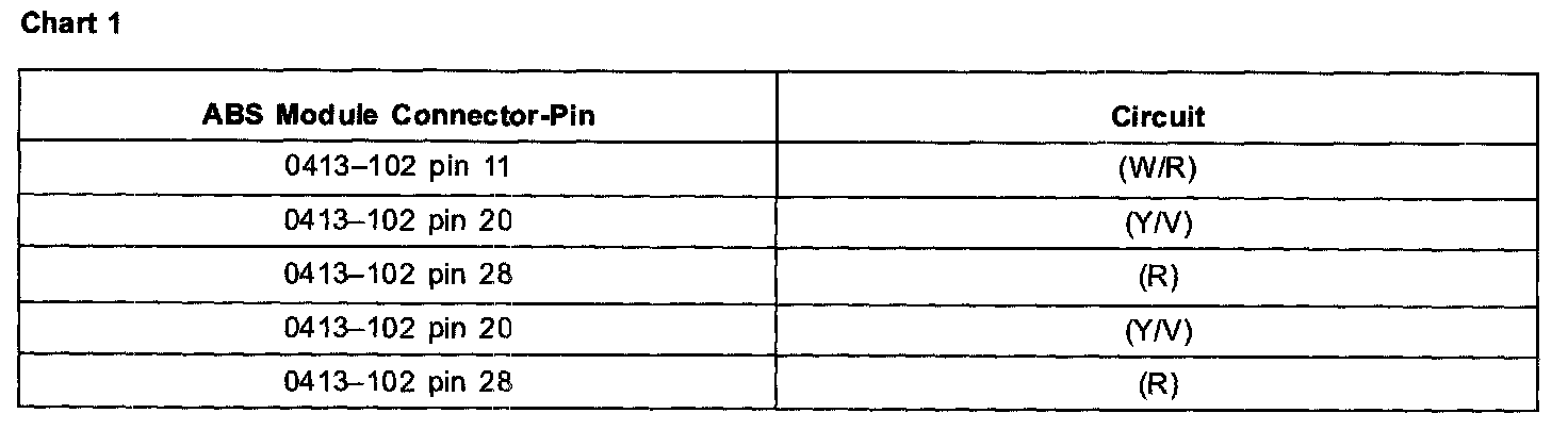
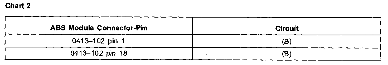
Chart 2:
Normal Operation
The ABS module communicates with the scan tool through circuit (GY). Voltage for the ABS module is provided by circuits (Y/V), (R) and (W/R). Circuit (BK) provides ground.
Possible Causes
- BJB fuse 17 (40 A)
- BJB fuse 33 (30 A)
- SJB fuse 20 (10 A)
- Circuit (GY) open, short to ground or voltage
- Circuit (Y/V) open
- Circuit (W/R) open
- Circuit (R) open
- Circuit (B) open
- ABS module
CAUTION: Use the correct probe adaptor(s) when making measurements. Failure to use the correct probe adaptor(s) may damage the connector.