Pinpoint Test G: The ABS Module Does Not Respond To The Scan Tool or No ISO 9141 Network Communication
Communications Network
Pinpoint Test
Pinpoint Test G: The ABS Module Does Not Respond To The Scan Tool or No ISO 9141 Network Communication
Refer to wiring Diagram Set 14, Module Communications Network for schematic and connector information. Diagrams By Number
Normal Operation
The scan tool communicates with the ISO 9141 network through the Data Link Connector (DLC). The ABS module communicates with the scan tool through the ISO 9141 communications network, circuit 70 (LB/WH).
This pinpoint test is intended to diagnose the following:
- Fuse
- Wiring, terminals or connectors
- ABS module
PINPOINT TEST G: THE ABS MODULE DOES NOT RESPOND TO THE SCAN TOOL OR NO ISO 9141 NETWORK COMMUNICATION
NOTICE: Use the correct probe adapter(s) when making measurements. Failure to use the correct probe adapter(s) may damage the connector.
NOTE: Most faults are due to connector and/or wiring concerns. Carry out a thorough inspection and verification before proceeding with the Pinpoint Test. Inspection and Verification
NOTE: Failure to disconnect the battery when instructed will result in false resistance readings. Refer to Battery.
-------------------------------------------------
G1 CHECK THE DLC PINS FOR DAMAGE
- Ignition OFF.
- Disconnect the scan tool from the DLC.
- Inspect DLC pin 7 for damage.
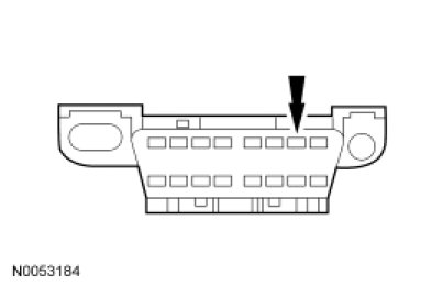
- Is DLC pin 7 OK?
Yes
GO to G2.
No
REPAIR the DLC as necessary. CLEAR the DTCs. REPEAT the network test with the scan tool.
-------------------------------------------------
G2 CHECK THE ISO 9141 CIRCUIT BETWEEN THE ABS MODULE AND THE DLC FOR AN OPEN
- Disconnect: ABS Module C135.
- Measure the resistance between the ABS module C135-16, circuit VDB10 (GY), harness side and the DLC C251-7, circuit VDB10 (GY), harness side.
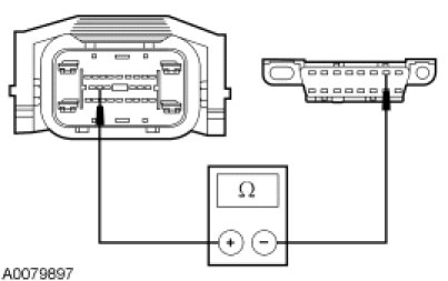
- Is the resistance less than 5 ohms?
Yes
GO to G3.
No
REPAIR the circuit. CLEAR the DTCs. REPEAT the network test with the scan tool.
-------------------------------------------------
G3 CHECK THE ISO 9141 NETWORK FOR A SHORT TO GROUND
- Measure the resistance between the DLC C251-7, circuit VDB10 (GY), harness side and ground.
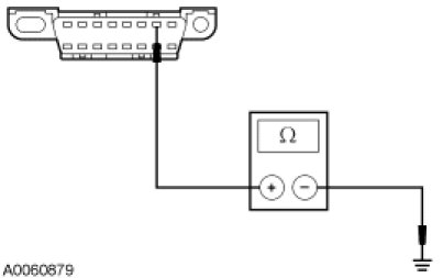
- Is the resistance greater than 10,000 ohms?
Yes
GO to G4.
No
REPAIR the circuit. CLEAR the DTCs. REPEAT the network test with the scan tool.
-------------------------------------------------
G4 CHECK THE ISO CIRCUIT FOR A SHORT TO VOLTAGE
NOTE: The ABS module must be disconnected for this test step to be accurate.
- Ignition ON.
- Measure the voltage between the DLC C251-7, circuit VDB10 (GY), harness side and ground.
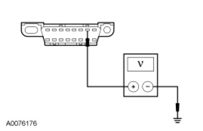
- Is any voltage indicated?
Yes
REPAIR the circuit. CLEAR the DTCs. REPEAT the network test with the scan tool.
No
GO to G5.
-------------------------------------------------
G5 CHECK THE ABS MODULE VOLTAGE SUPPLY CIRCUITS FOR AN OPEN
- Measure the voltage between the ABS module, harness side and ground as follows:
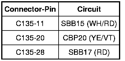
- Are the voltages greater than 10 volts?
Yes
GO to G6.
No
VERIFY the Battery Junction Box (BJB) fuses 17 (40A) and 33 (30A) and the SJB fuse 20 (10A) are OK. If OK, REPAIR the circuit in question. If not OK, REFER to the Wiring Diagrams to identify the possible causes of the circuit short. CLEAR the DTCs. REPEAT the network test with the scan tool.
-------------------------------------------------
G6 CHECK THE ABS MODULE GROUND CIRCUITS FOR AN OPEN
- Ignition OFF.
- Disconnect: Negative Battery Cable.
- Measure the resistance between the ABS module, harness side and ground as follows:
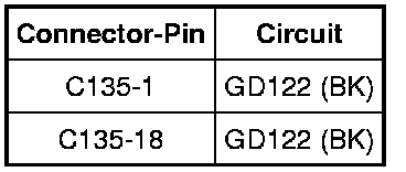
- Are the resistances less than 5 ohms?
Yes
CONNECT the negative battery cable. GO to G7.
No
REPAIR the circuit. CONNECT the negative battery cable. CLEAR the DTCs. REPEAT the network test with the scan tool.
-------------------------------------------------
G7 CHECK FOR CORRECT ABS MODULE OPERATION
- Disconnect the ABS module connector.
- Check for:
- corrosion
- damaged pins
- pushed-out pins
- Connect the ABS module connector and make sure it seats correctly.
- Operate the system and verify the concern is still present.
- Is the concern still present?
Yes
INSTALL a new ABS module. CLEAR the DTCs. REPEAT the network test with the scan tool.
No
The system is operating correctly at this time. The concern may have been caused by a loose or corroded connector. CLEAR the DTCs. REPEAT the network test with the scan tool.
-------------------------------------------------