Part 2
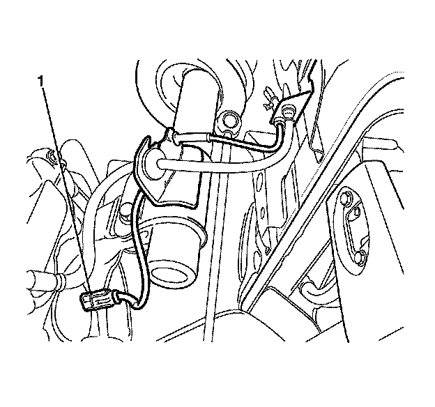
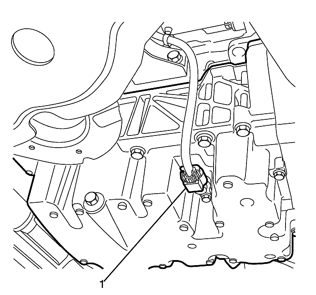
81. Disconnect the front wheel speed sensor electrical harness connector (1) and position away from the subframe and suspension components.
82. Repeat for the opposite side.
Note:
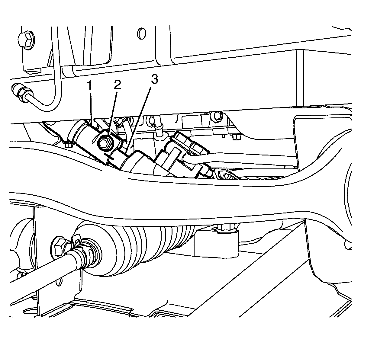
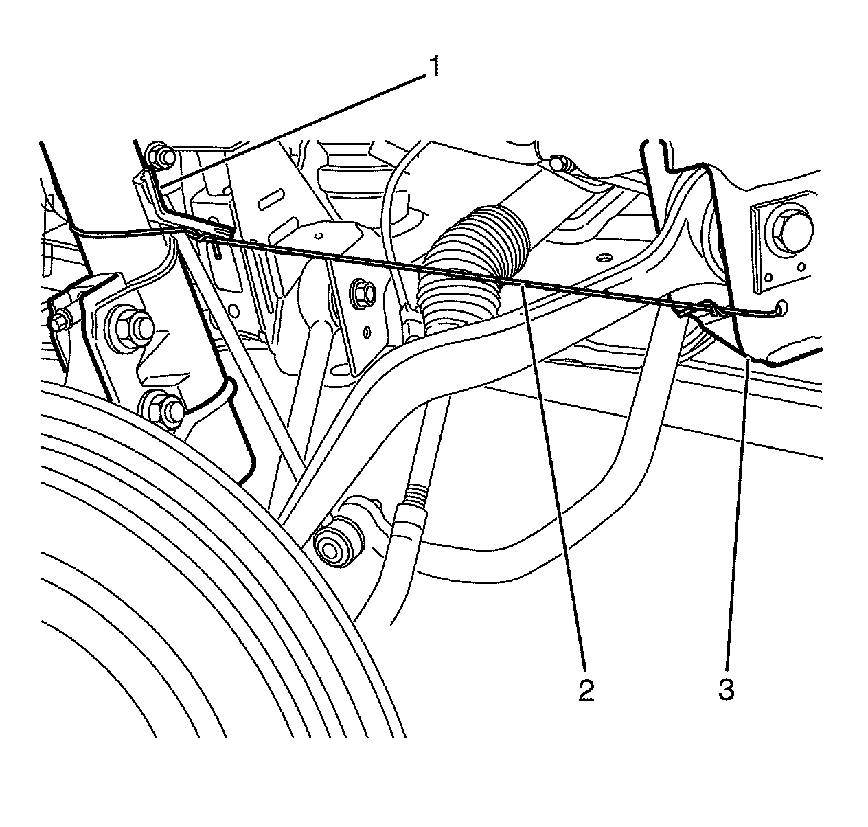
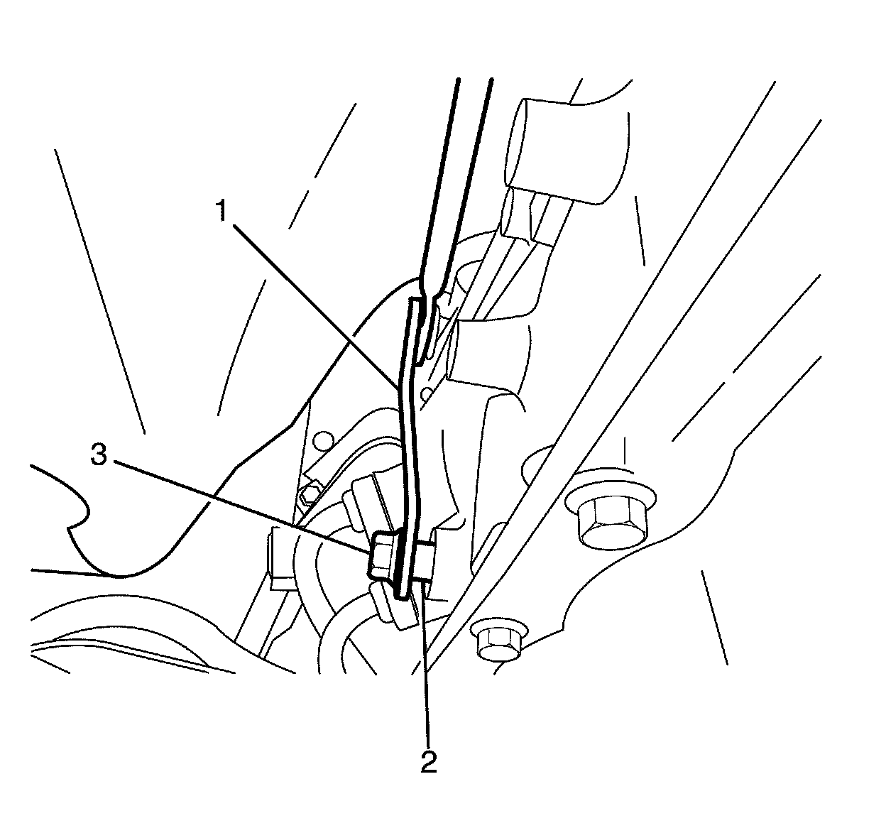
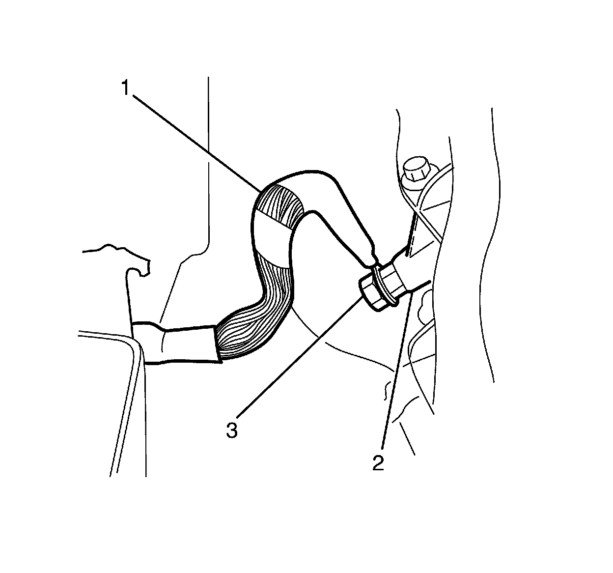
Observing the orientation of the intermediate steering shaft (1) with reference to the pinion shaft (3) will minimize the potential of incorrect steering column assembly alignment.
83. Mark the intermediate steering shaft (1) with reference to the pinion shaft (3).
Note:
* Bolts with micro-encapsulated thread sealant must be discarded after removal.
* Make sure the bolt threaded hole is thoroughly cleaned and all micro-encapsulated thread sealant is removed.
84. Remove the intermediate steering shaft to pinion shaft retaining bolt (2).
85. Remove the intermediate shaft (1) from the pinion shaft (3).
* Discard the bolt.
* Clean the bolt threaded hole.
86. Lower the vehicle.
Note:
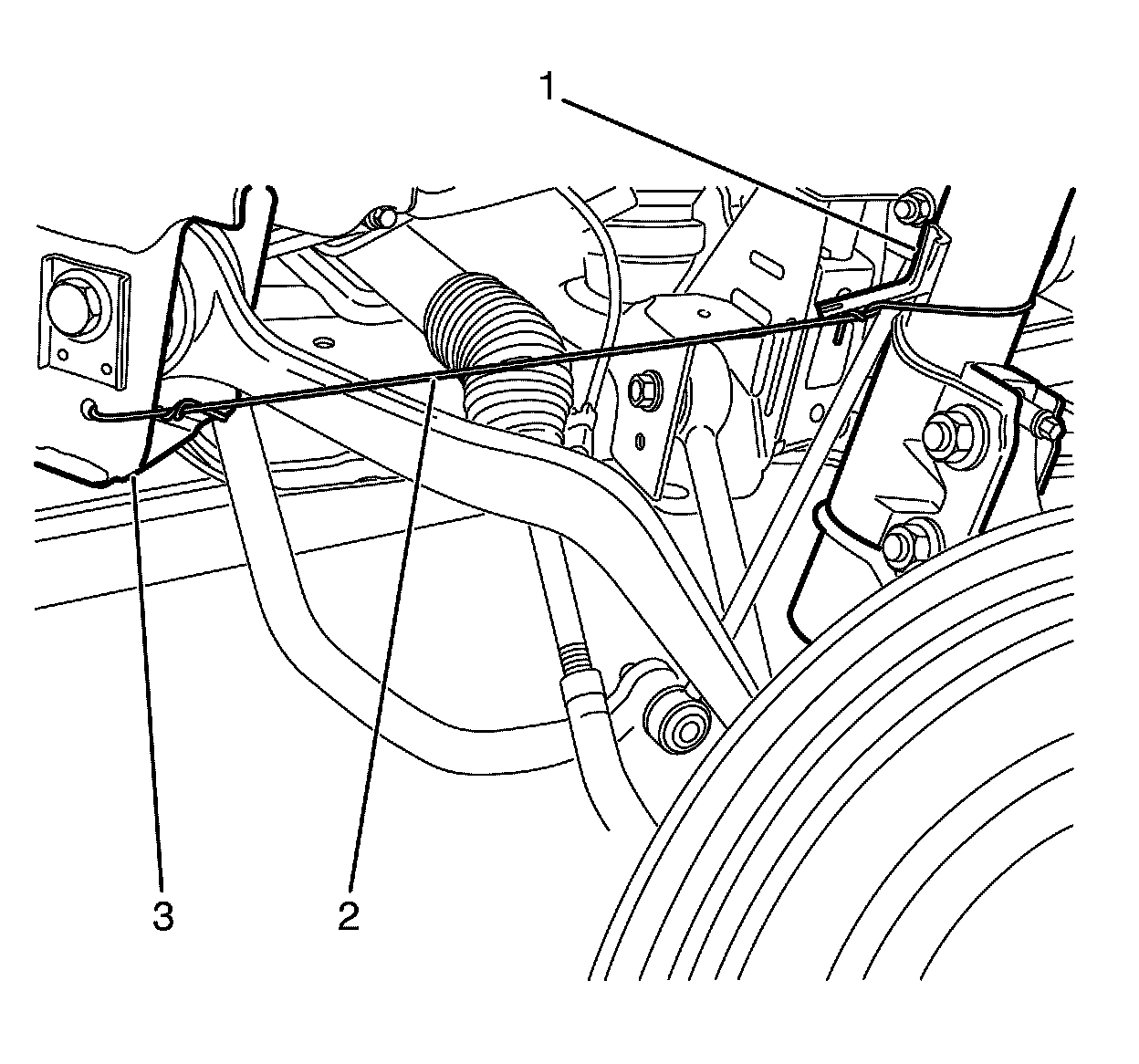
The strut assembly (1) must be secured to the subframe (3) to prevent damage to the front wheelhouse liner, fenders and suspension components.
87. Secure the strut assembly (1) to the subframe (3) using heavy mechanics wire or equivalent (2).
88. Repeat for the opposite side.

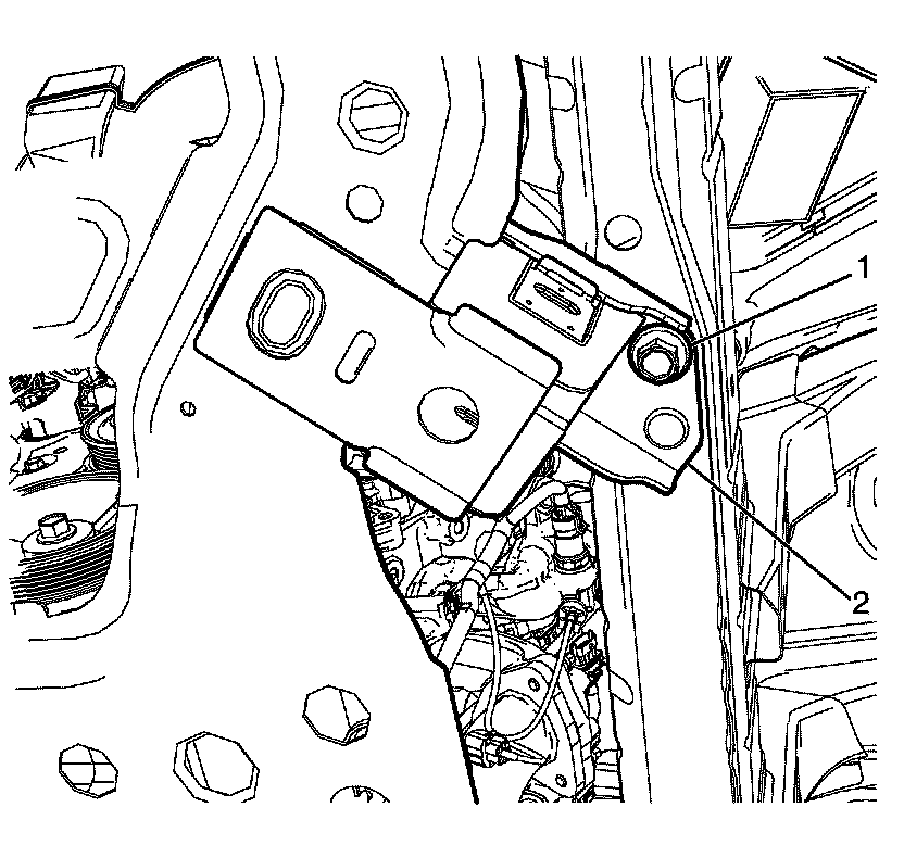
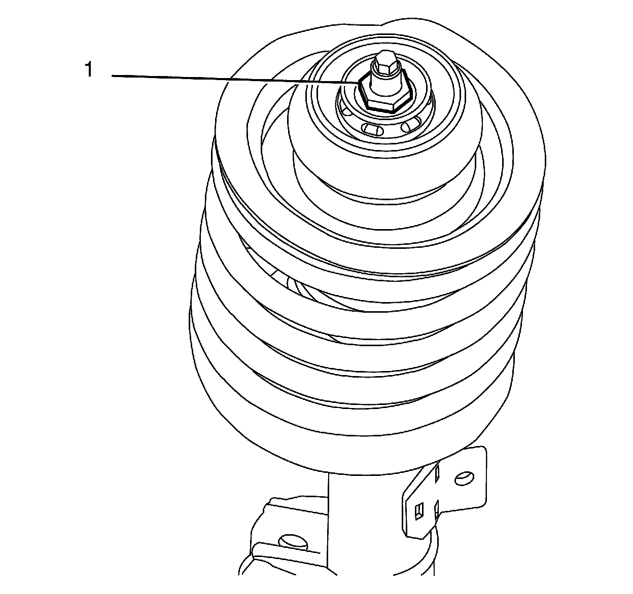
89. Remove the stud dust cover (1) from the strut assembly to front wheelhouse retaining nut (2).
Note:
* Support the strut assembly (4) before removing the front wheelhouse retaining nut (2).
* Hold the strut piston shaft (4) with a suitable tool when removing the front wheelhouse retaining nut.
90. Remove the strut assembly to front wheelhouse retaining nut (2).
Discard the nut.
91. Remove the strut assembly to front wheelhouse retaining plate (3).
92. Repeat for the opposite side.
93. Support the powertrain with a suitable lift table.
94. Remove the transmission support to body retaining bolts (1).

95. Remove the subframe to body rear retaining bolts (1).
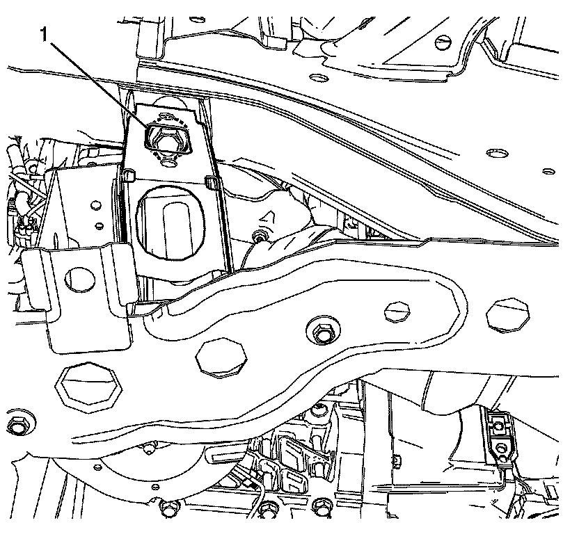
Note:
For graphical illustration the left side is shown. The right side is similar.
96. Remove the subframe to body front retaining bolt (1).
97. Repeat for the opposite side.
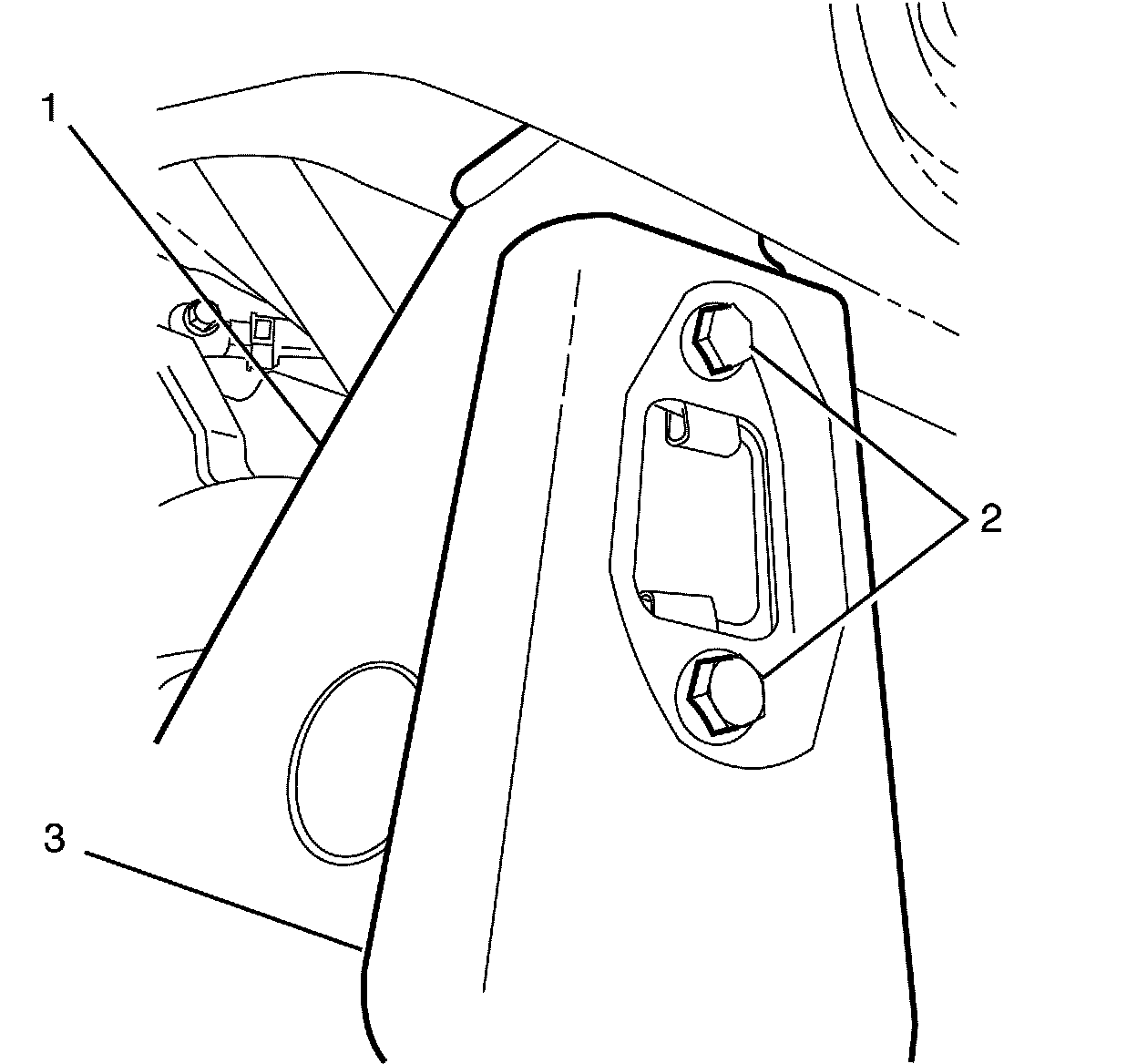
98. Remove the subframe reinforcement plate to subframe retaining bolts (2).
99. Remove the subframe reinforcement plate (3) from the subframe (1).
100. Repeat for the opposite side.
Note:
For graphical illustration the left side is shown. The right side is similar.
101. Remove the subframe to body retaining bolt (1).
102. Repeat for the opposite side.
Note:
Make sure that all the hoses, harnesses, pipes and front struts are not damaged during the powertrain removal process.
103. With the aid of an assistant, lower the table or raise the vehicle to remove the powertrain with the subframe assembly from the vehicle.
104. Remove the engine and transmission wiring harness and related components.
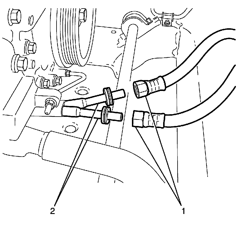
105. Remove the transmission cooler line clamp to alternator mounting bracket retaining nut (1).
106. Remove the transmission cooler line clamp (3) and transmission cooler lines (2) from the alternator mounting bracket (4).
Caution:
Refer to Fastener Caution Fastener Caution.
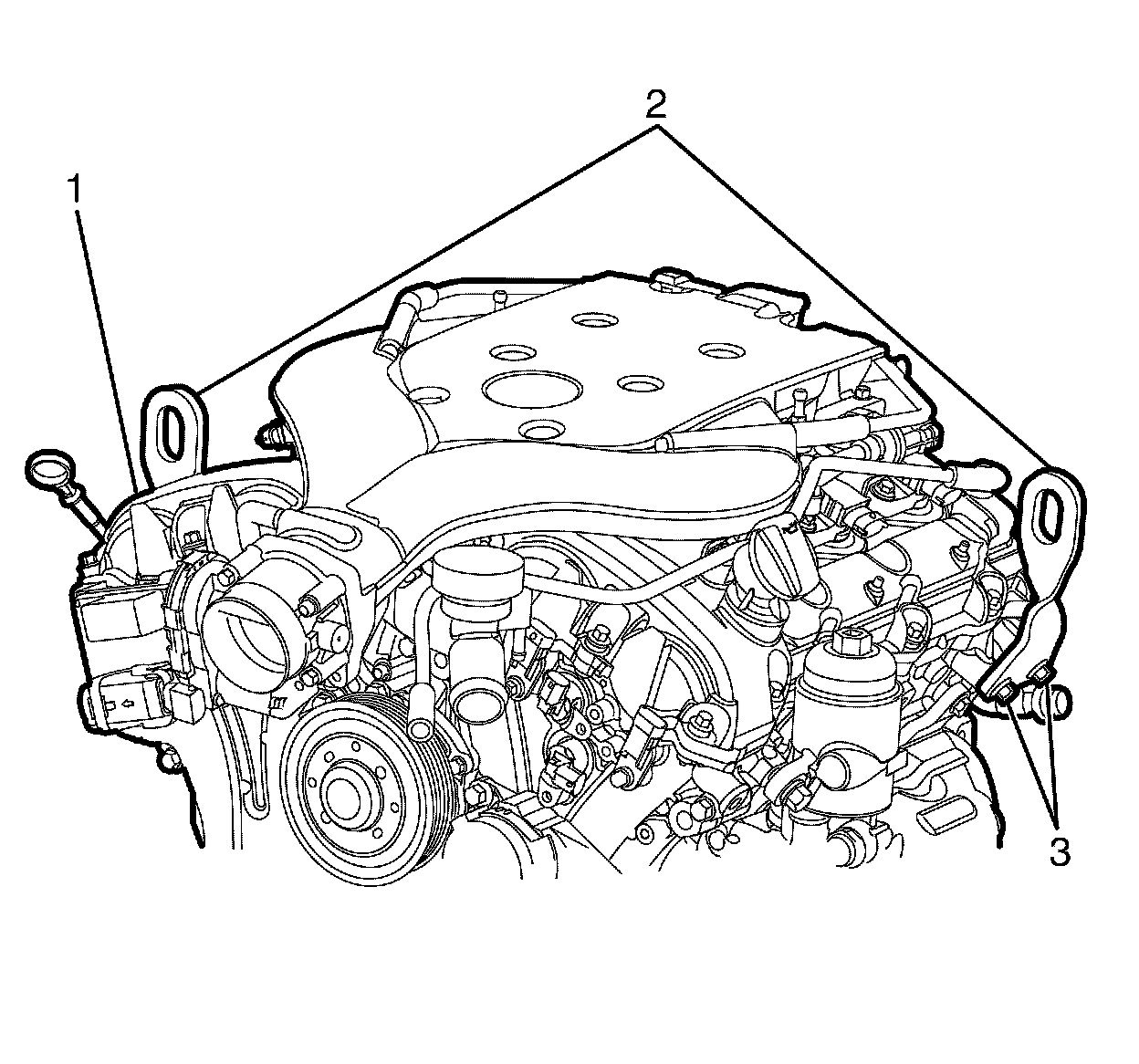
107. Install the engine lift brackets EN 46114 to the cylinder heads. Tighten the engine lift bracket bolts to 50 Nm (36 lb ft).
108. Install a suitable lifting crane to the engine lift brackets (2) and raise the lifting crane to support the engine.
109. Position a second powertrain lift table below the transmission.
110. Remove the transmission from the engine.
111. Rest the transmission on the second lift table after it has been removed.
112. Remove the engine flywheel. Refer to Engine Flywheel Removal 8. Engine Flywheel Removal.
113. Remove the catalytic converters. Refer to:
* Catalytic Converter Replacement - Right Side (LFX) Catalytic Converter Replacement - Right Side
* Catalytic Converter Replacement - Left Side (LFX) Catalytic Converter Replacement - Left Side
114. Remove the drive belt. Refer to Drive Belt Replacement Service and Repair.
Note:
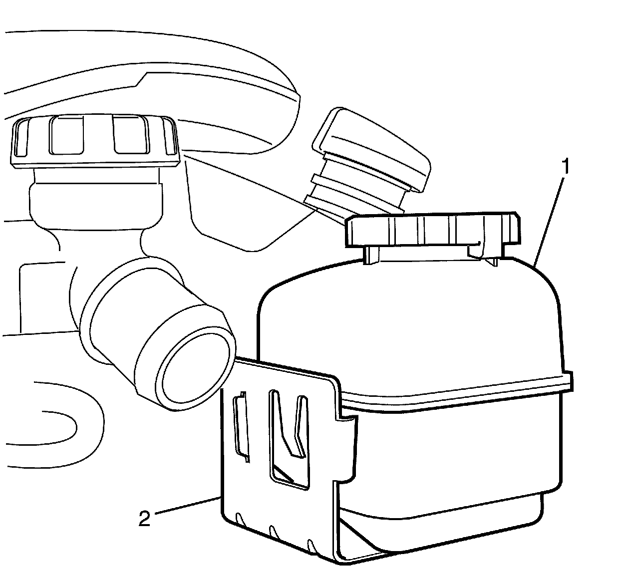
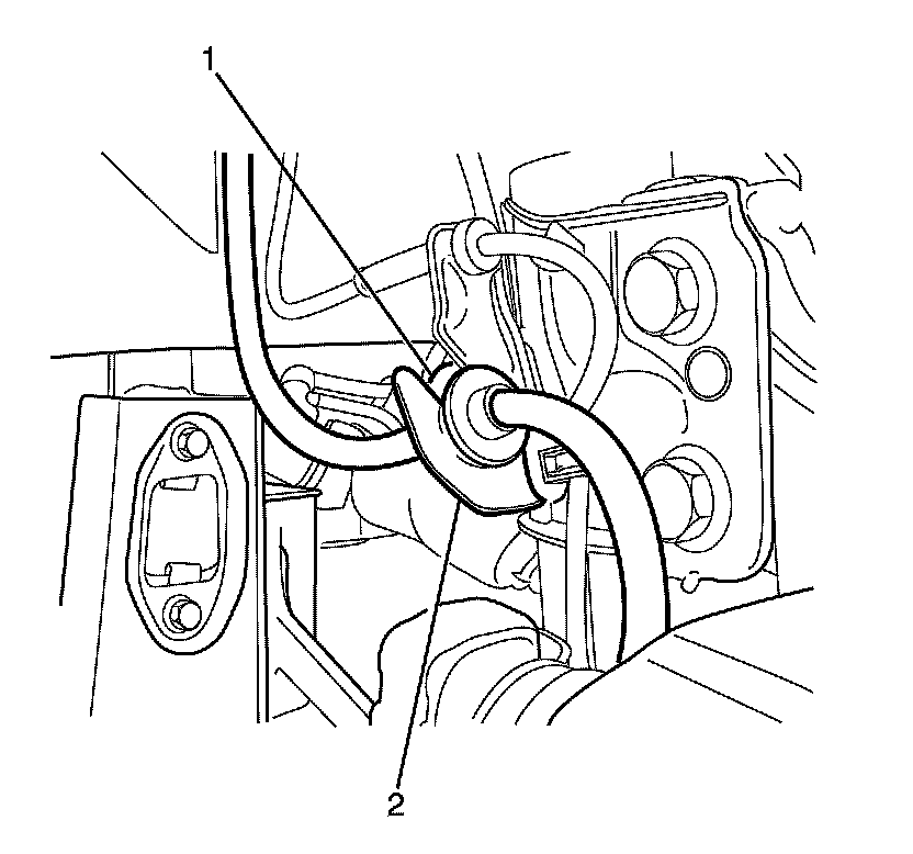
The locking tang on the power steering reservoir bracket must be released before removing the power steering reservoir (1) from the power steering reservoir bracket (2).
115. Remove power steering fluid reservoir (1) from the power steering fluid reservoir bracket (2).
Note:
* DO NOT disconnect the power steering pipes or hoses.
* Bolts with micro-encapsulated thread sealant must be discarded after removal.
* Make sure all the threaded bolt holes are thoroughly cleaned and all micro-encapsulated thread sealant is removed.
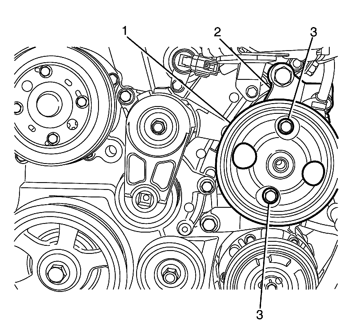
116. Remove the power steering pump to power steering pump bracket retaining bolts (3).
* Discard the bolts.
* Clean the threaded bolt holes.
117. Remove the power steering pump (1) from the power steering pump bracket (2) and position the power steering pump away from the engine.
118. Remove the A/C compressor. Refer to Air Conditioning Compressor Replacement (LFX) Air Conditioning Compressor ReplacementAir Conditioning Compressor Replacement (L77) Air Conditioning Compressor Replacement.
119. Remove the A/C compressor mounting bracket. Refer to Air Conditioning Compressor Bracket Replacement (LFX) Air Conditioning Compressor Bracket ReplacementAir Conditioning Compressor Bracket Replacement (L77) Air Conditioning Compressor Bracket Replacement.
120. Remove the alternator. Refer to Generator Replacement (L77) Generator ReplacementGenerator Replacement (LFX) Generator Replacement.
121. Remove the alternator mounting bracket. Refer to Generator Bracket Replacement (L77) Generator Bracket ReplacementGenerator Bracket Replacement (LFX) Generator Bracket Replacement.
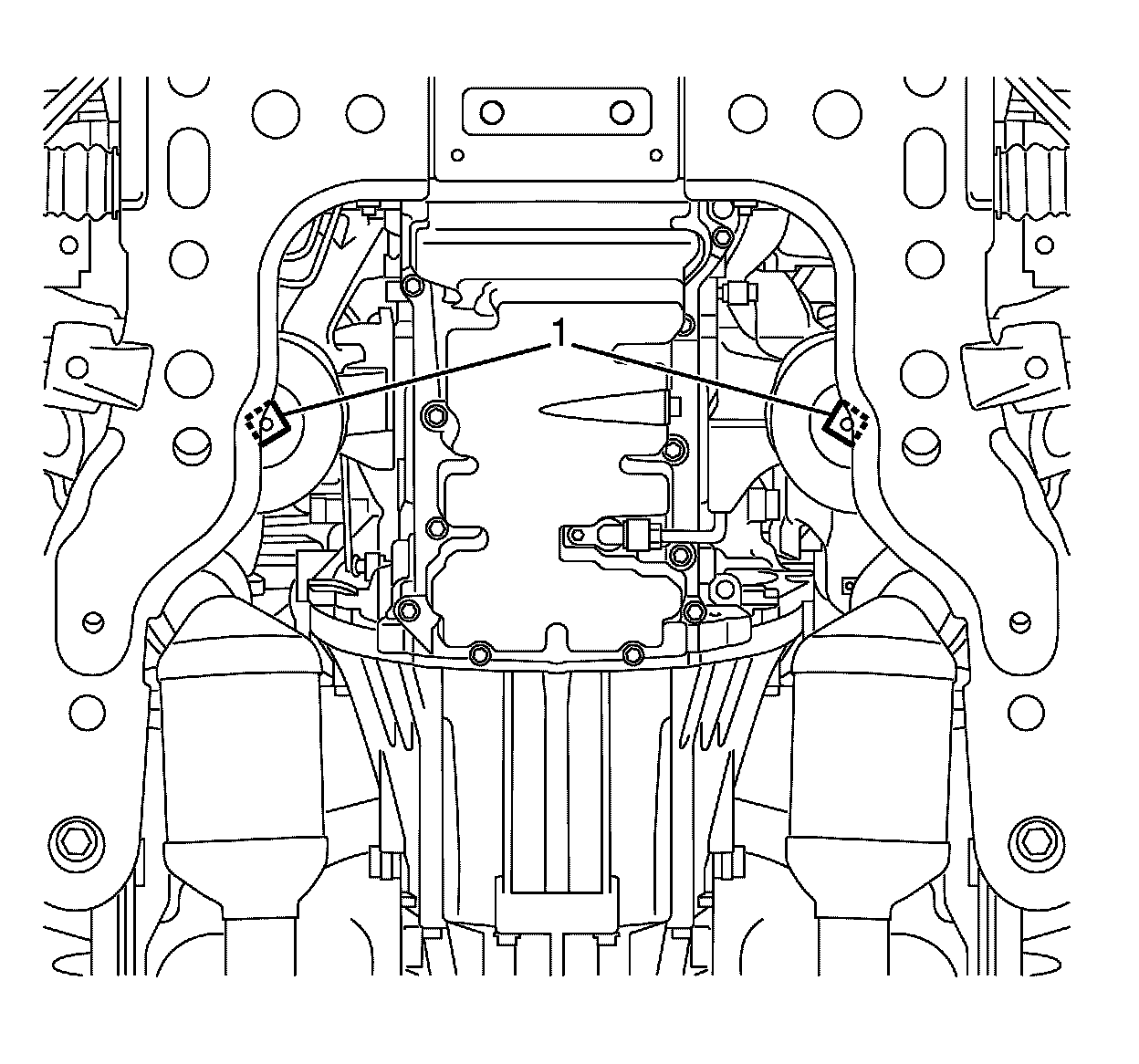
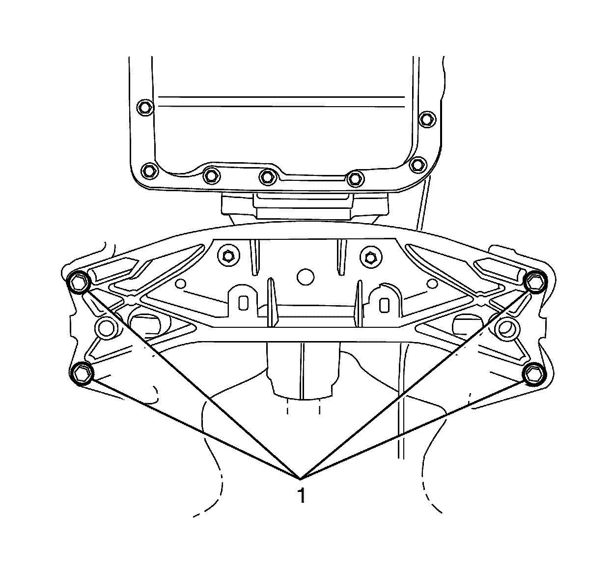
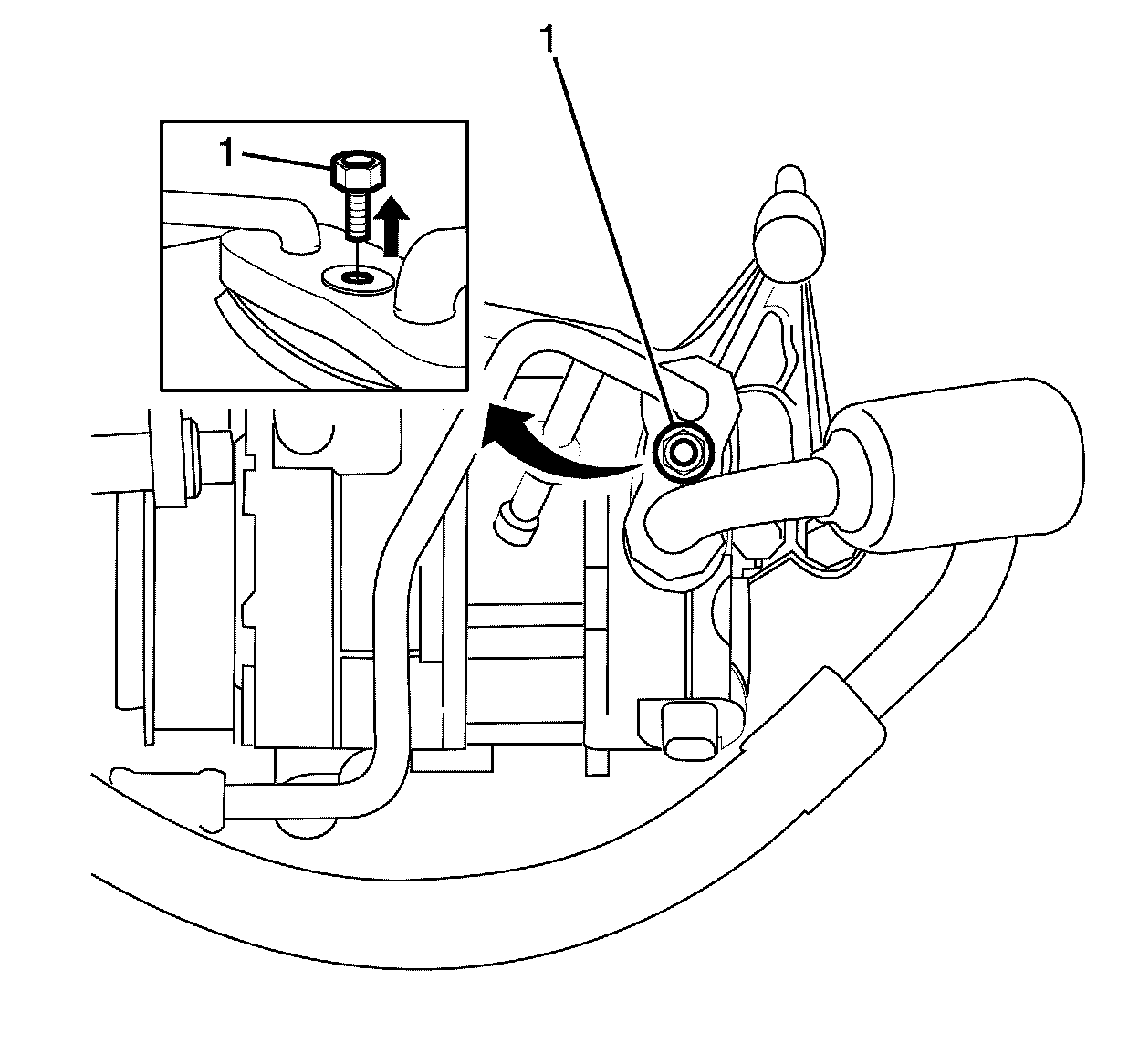
122. Remove the lower engine mount retaining nuts (1).
123. Using a suitable lifting crane, raise the engine until it is free from the engine mount stud.
124. Remove the engine mount brackets with the engine mounts. Refer to:
* Engine Mount Bracket Replacement - Left Side Engine Mount Bracket Replacement - Left Side
* Engine Mount Bracket Replacement - Right Side Engine Mount Bracket Replacement - Right Side
125. Remove the engine from the subframe.
If required mount the engine on a suitable engine stand.
Installation Procedure
1. Install the engine mount brackets with the engine mounts to the engine. Refer to:
* Engine Mount Bracket Replacement - Left Side Engine Mount Bracket Replacement - Left Side
* Engine Mount Bracket Replacement - Right Side Engine Mount Bracket Replacement - Right Side
2. Use the lift crane to install the engine to the subframe.
3. Raise the engine with the lift crane to partially support the engine.
4. Install the subframe to the engine.
5. Install the lower engine mount retaining nuts (1). Tighten the bolts to 80 Nm (59 lb ft).
6. Install the alternator bracket. Refer to Generator Bracket Replacement (L77) Generator Bracket ReplacementGenerator Bracket Replacement (LFX) Generator Bracket Replacement.
7. Install the alternator. Refer to Generator Replacement (L77) Generator ReplacementGenerator Replacement (LFX) Generator Replacement.
8. Install the A/C compressor mounting bracket. Refer to Air Conditioning Compressor Bracket Replacement (LFX) Air Conditioning Compressor Bracket ReplacementAir Conditioning Compressor Bracket Replacement (L77) Air Conditioning Compressor Bracket Replacement.
9. Install the A/C compressor. Refer to Air Conditioning Compressor Replacement (LFX) Air Conditioning Compressor ReplacementAir Conditioning Compressor Replacement (L77) Air Conditioning Compressor Replacement.
10. Install the power steering pump (1) to the power steering pump bracket (2).
11. Install the NEW power steering pump to power steering pump bracket retaining bolts (3) and tighten to 27 Nm (20 lb ft).
Note:
Make sure the power steering reservoir (2) and the power steering reservoir bracket locking tang (1) are engaged to avoid an induced rattle condition.
12. Install the power steering fluid reservoir (1) to the power steering fluid reservoir bracket (2).
13. Install the drive belt. Refer to Drive Belt Replacement Service and Repair.
14. Install the catalytic converters. Refer to Catalytic Converter Replacement - Left Side (LFX) Catalytic Converter Replacement - Left Side and Catalytic Converter Replacement - Right Side (LFX) Catalytic Converter Replacement - Right Side.
15. Install the flywheel. Refer to Engine Flywheel Removal 8. Engine Flywheel Removal.
16. Install the transmission to the engine.
17. Install the transmission cooler line clamp (3) and transmission cooler lines (2) to the alternator mounting bracket (4).
18. Install the transmission cooler line clamp to alternator mounting bracket retaining nut (1) and tighten to 22 Nm (16 lb ft) .
19. Install the engine and transmission wiring harness and related components.
20. Lower the engine, transmission, front suspension and subframe assembly onto the lift table.
Note:
Make sure that all the hoses, harnesses, pipes and front struts are not damaged during the powertrain installation process.
21. With the aid of an assistant, raise the table or lower the vehicle to install the engine, transmission, front suspension and subframe assembly to the vehicle.
Note:
For graphical illustration the left side is shown. The right side is similar.
22. Install the subframe to body retaining bolts (1) and tighten to 160 Nm (118 lb ft).
23. Repeat for the opposite side.
Note:
For graphical illustration the left side is shown. The right side is similar.
24. Install the subframe to body front retaining bolts (1) and tighten to 160 Nm (118 lb ft).
25. Repeat for the opposite side.
26. Install the transmission support to body retaining bolts (1) and tighten to 58 Nm (43 lb ft).
27. Install the subframe to body rear retaining bolts (1) and tighten to 240 Nm (177 lb ft).
28. Install the subframe reinforcement plate (3) to the subframe (1).
29. Install the subframe reinforcement plate to subframe retaining bolts (2) and tighten to 17 Nm (13 lb ft).
30. Repeat for the opposite side.
31. Remove the lift table from the vehicle.
32. Partially lower the vehicle.
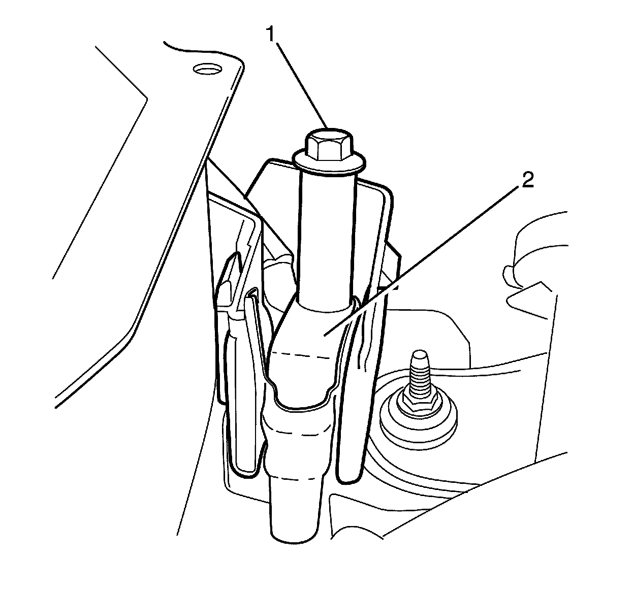
33. Check the torque of the strut assembly retaining nut (1). Tighten the nut to 75 Nm (55 lb ft).
34. Repeat for the opposite side.
Note:
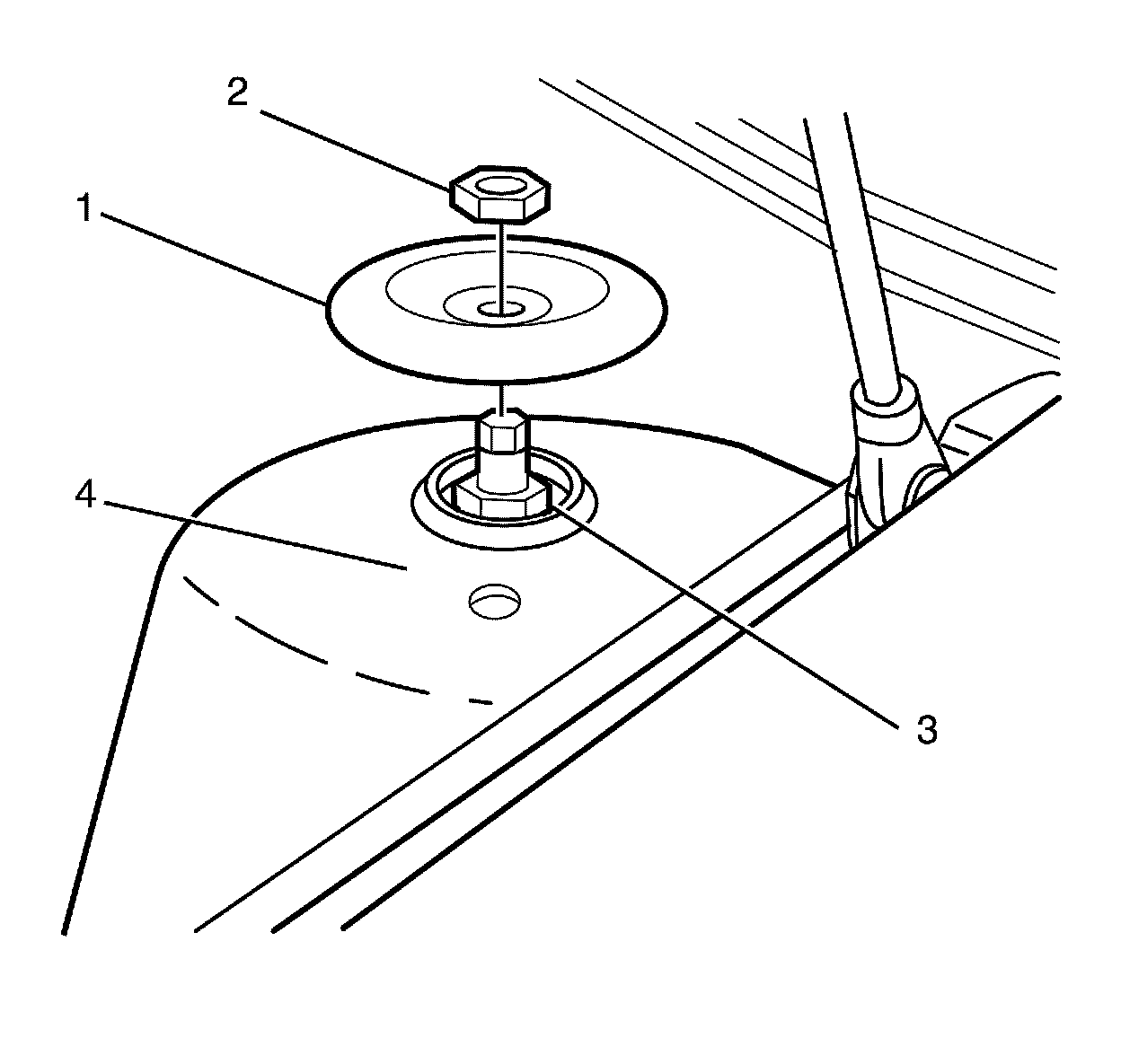
For graphical illustration the left side is shown. The right side is similar.
35. Install the strut assembly (3) to the vehicle (4).
36. Install strut assembly to body retaining plate (1).
37. Install the NEW strut assembly to body retaining nut (2) and tighten to 55 Nm (41 lb ft).
38. Repeat for the opposite side.
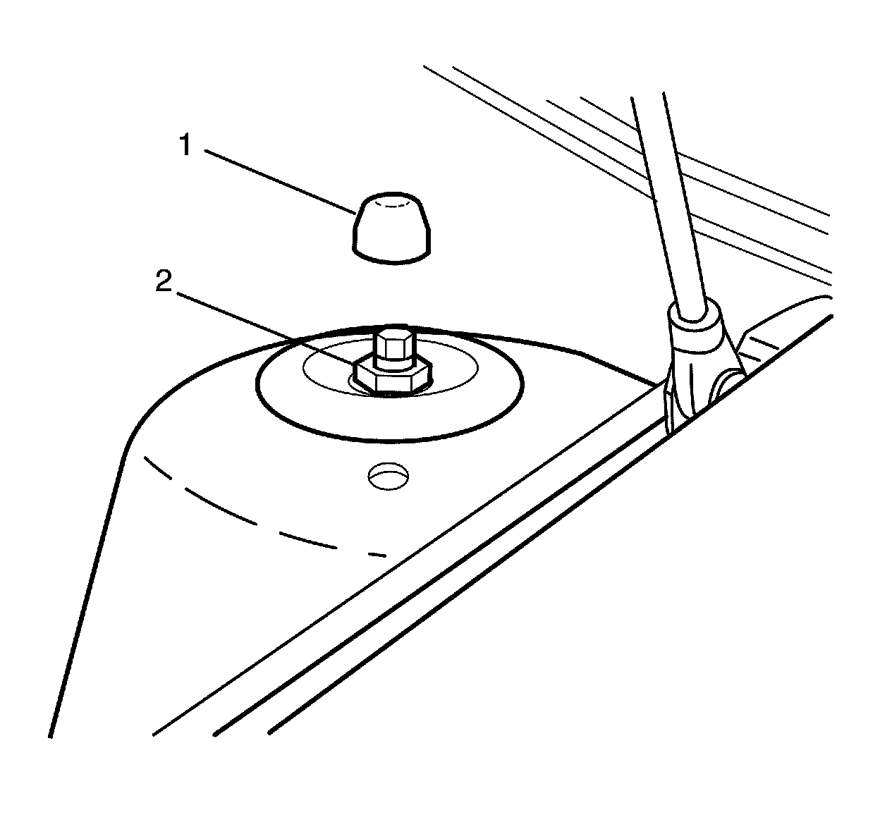
Note:
For graphical illustration the left side is shown. The right side is similar.
39. Install the dust cover (1) to the strut assembly to body retaining nut (2).
40. Repeat for the opposite side.
41. Partially raise the vehicle.
42. Remove the heavy mechanics wire or equivalent (2).
43. Repeat for the opposite side.
Note:
The intermediate steering shaft and pinion shaft must be installed in the same position as it was before it was removed.
44. Align the mark previously made and install the intermediate steering shaft (1) to the pinion shaft (3).
45. Install a NEW intermediate steering shaft to pinion shaft retaining bolt (2) and tighten to 25 Nm (18 lb ft).
46. Connect the wheel speed sensor electrical harness connector (1) to the wheel speed sensor.
47. Repeat for the opposite side.
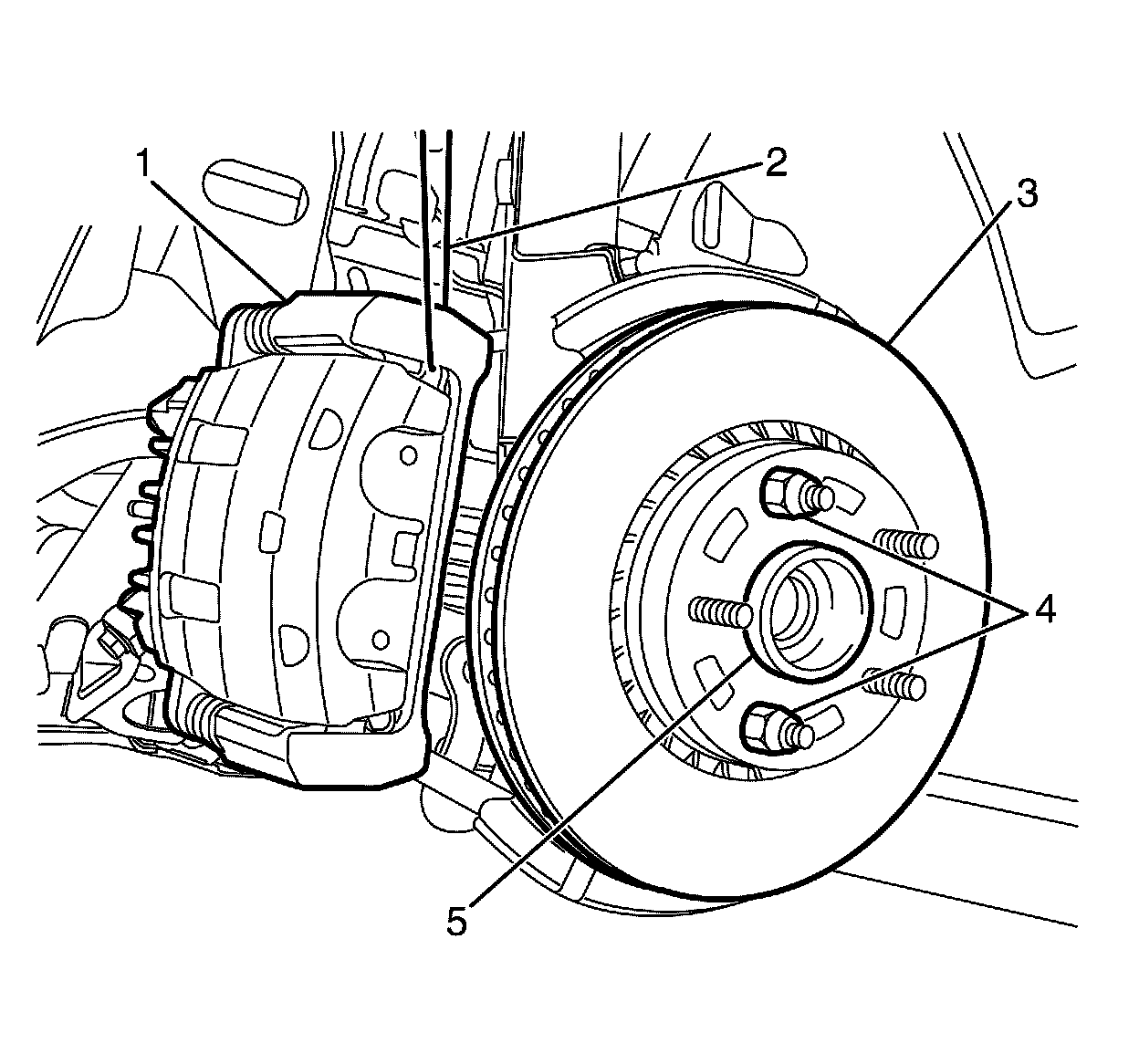
48. Remove the heavy mechanic's wire, or equivalent support (2) from the brake caliper (1).
49. Remove the wheel nuts (4) retaining the brake disc (3) to the hub (5).
50. Repeat for the opposite side.
Caution:
Make sure the brake hose is not twisted or kinked after installation. Damage to the hose could result.
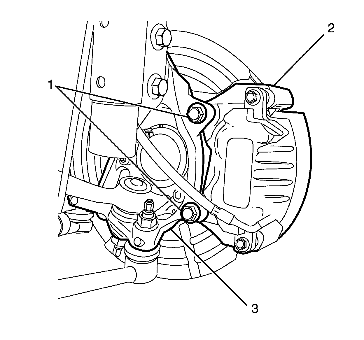
51. Install the brake caliper assembly (2) to the steering knuckle (3).
52. Install the NEW brake caliper anchor plate to knuckle retaining bolts (1) and tighten to 60 Nm (44 lb ft) plus 120 degrees.
53. Repeat for the opposite side.
Caution:
Make sure the brake hose is not twisted or kinked after installation. Damage to the hose could result.
54. Install the brake hose (1) to the strut mounted brake hose retaining bracket (2).
55. Install the front wheels. Refer to Tire and Wheel Removal and Installation Service and Repair.
56. Repeat for the opposite side.
Note:
Steps 58 to 62 are for vehicles fitted with a manual transmission.
57. Install the starter motor. Refer to Starter Replacement (L77) Service and RepairStarter Replacement (LFX) Service and Repair.
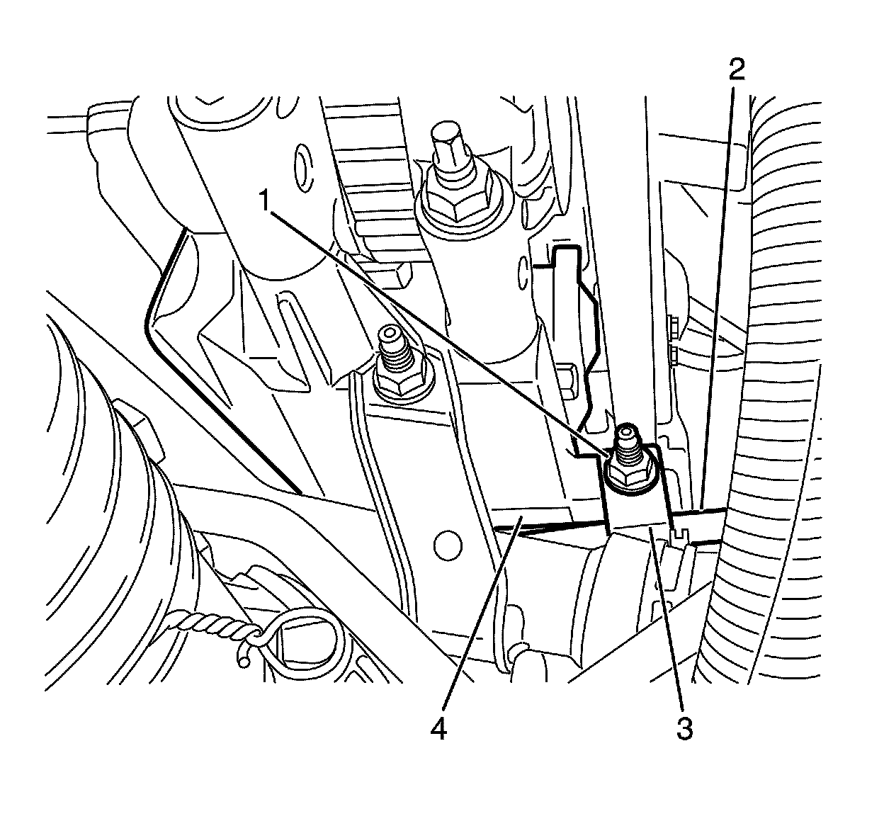
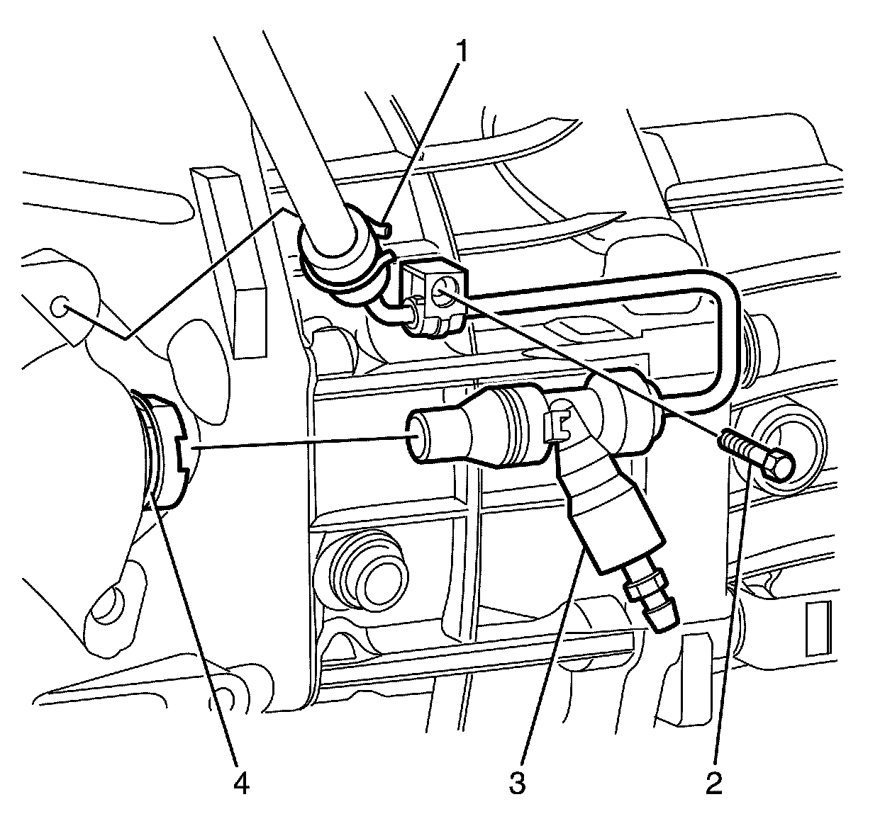
58. Install the bleeder assembly (3).
59. Install the bleeder assembly securing clip (4).
60. Install the concentric actuator cylinder feed pipe bracket to transmission retaining bolt (2). Tighten the nut to 7 Nm (62 lb ft).
Note:
Listen for an audible click to confirm correct fitting of the flexible hose securing clip.
61. Install the flexible hose securing clip.
62. Install the gearshift lever boot.
63. Install the shift selector linkage rod (1) to the shift selector shaft (2).
64. Install the shift selector linkage rod to shift selector shaft retaining nut (3) and tighten to 15 Nm (11 lb ft).
65. Install the propeller shaft. Refer to Propeller Shaft Replacement (Except 4L60) Propeller Shaft Replacement (Except 4L60).
66. Install the centre exhaust heat shield. Refer to Exhaust Heat Shield Replacement - Center Exhaust Heat Shield Replacement - Center.
67. Install the exhaust system. Refer to Exhaust System Replacement (V6) Service and RepairExhaust System Replacement (V8) Service and Repair.
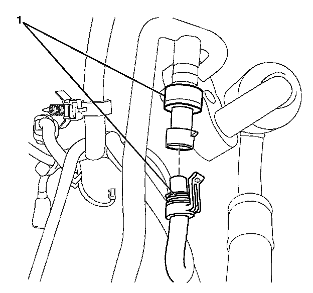
68. Connect the oil level/temperature sensor electrical connector (1).
69. Remove the plug or cap from the ends of the power steering cooler hoses (1).
70. Install the power steering cooler hoses (1).
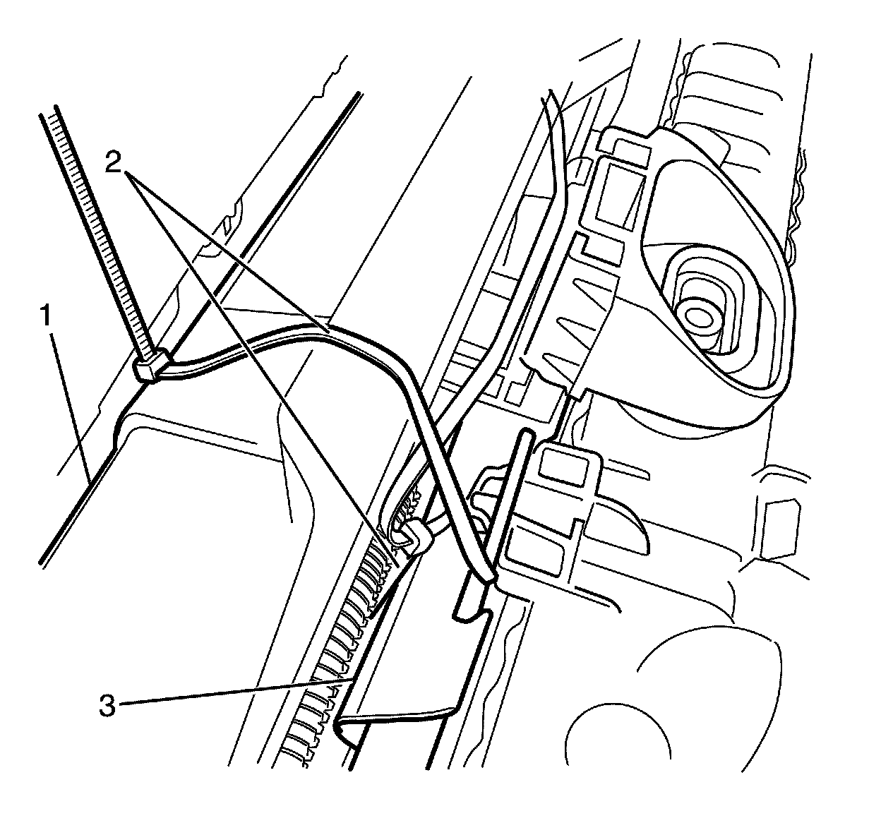
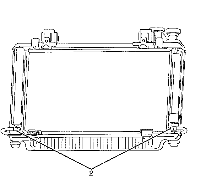
71. Remove the zip ties (2) or equivalent securing the radiator and condenser assembly (3) to the front end assembly (1).
72. Remove the plug or cap from the ends of the transmission cooler lines (2) and the flexible hoses (1).
73. Install the flexible hoses (1) to the transmission fluid lines (2). Refer to Metal Collar Quick Connect Fitting Service Service and Repair.

74. Remove the plug or cap from the ends of the fuel feed hose and fuel feed pipe.
75. Connect the fuel feed hose (2) to the fuel feed pipe. Refer to Metal Collar Quick Connect Fitting Service Service and Repair.
76. Remove the plug or cap from the ends of the EVAP purge hose and EVAP purge pipe.
77. Connect the EVAP purge hose (1) to the EVAP purge pipe. Refer to Plastic Collar Quick Connect Fitting Service Procedures.
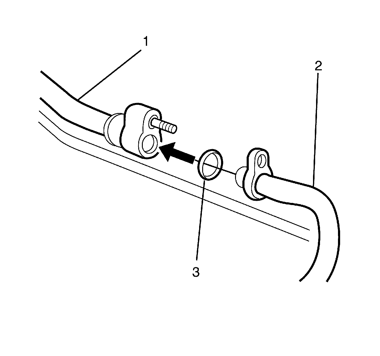
Note:
DO NOT coat the new sealing washer with oil. It must be fitted dry.
78. Remove the plug or cap from the ends from the upper suction pipe (1) and the lower suction pipe (2)
79. Install a NEW seal (3) to suction pipe (2).
80. Install the upper suction pipe (1) to the lower suction pipe (2).
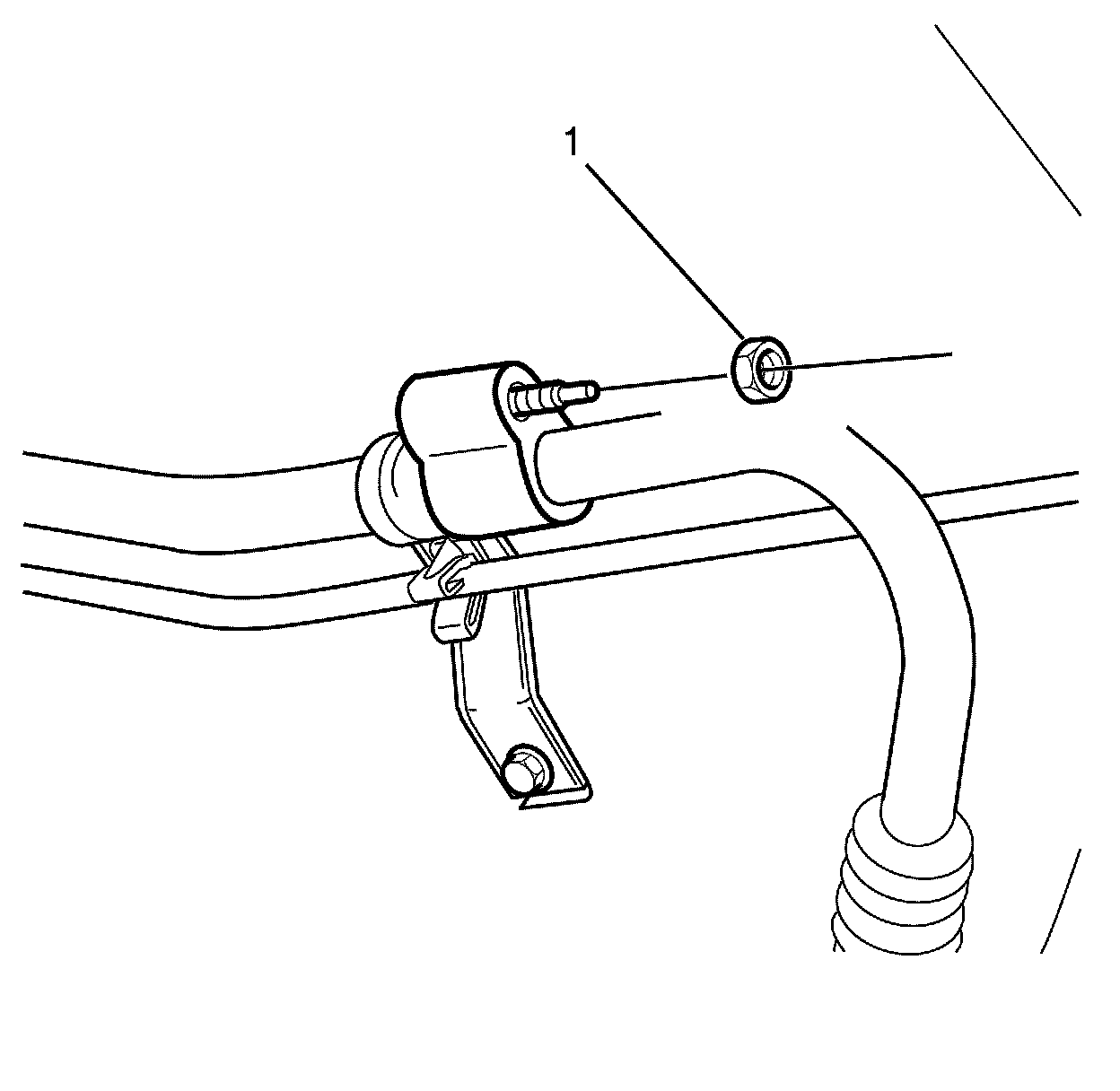
81. Install the A/C suction pipe pad to A/C suction pipe retaining nut (1) and tighten to 22 Nm (16 lb ft).

82. Remove the plug or cap from the ends from the A/C suction/discharge pipe (1) and the compressor ports.
Note:
DO NOT lubricate the A/C suction/discharge pipe seals. It must be fitted dry.
83. Fit the NEW A/C suction/discharge pipe seals (2) to the suction/discharge pipe.
84. Connect the A/C suction/discharge line pad (1) to the A/C compressor (3).
85. Install the suction/discharge line pad to A/C compressor retaining nut (1) and tighten to 22 Nm (16 lb ft).
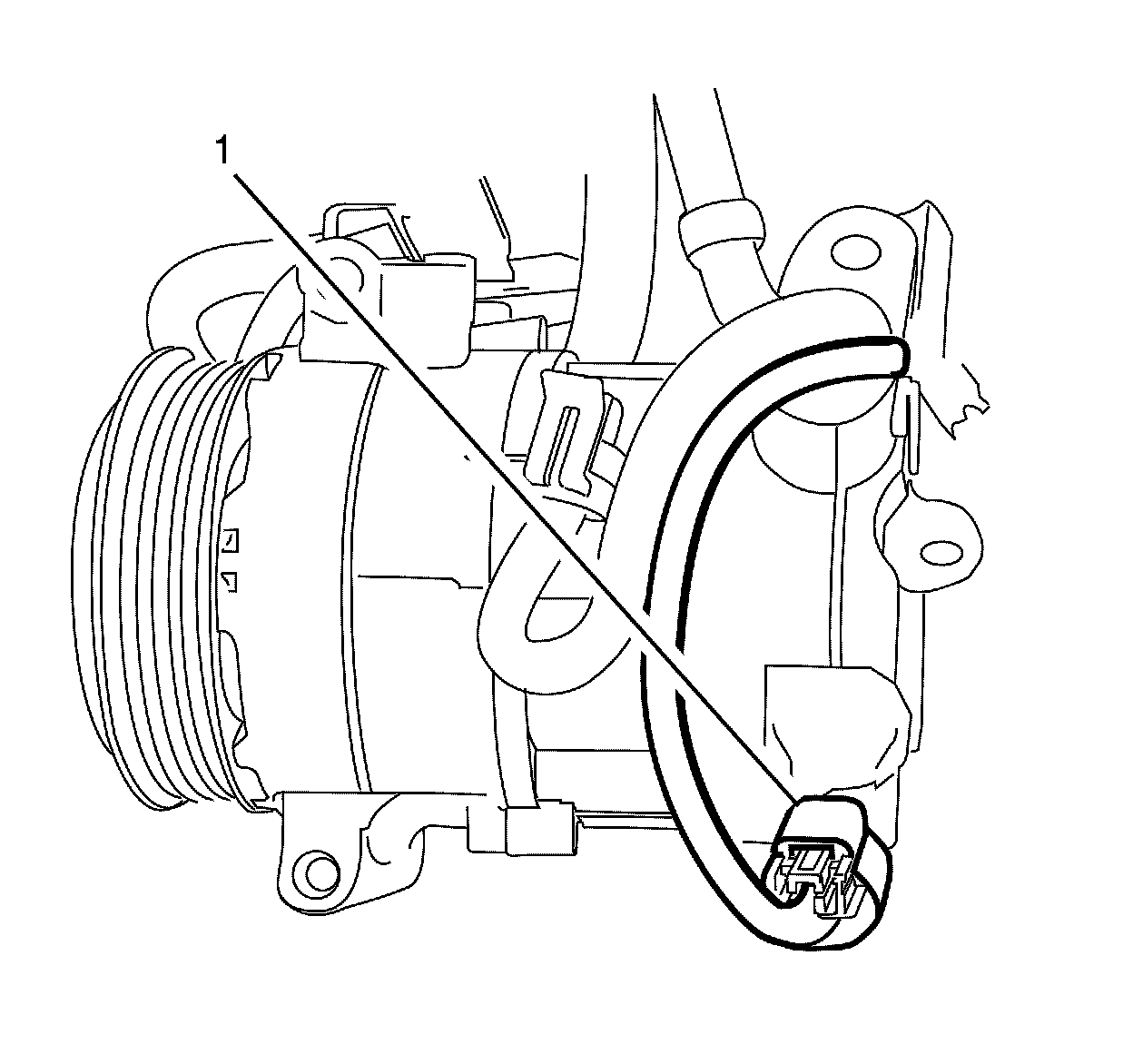
86. Connect the A/C compressor electrical connector (1) to the A/C compressor.
87. Connect the A/C pressure transducer electrical connector (1) to the A/C pressure transducer.
88. Remove the plug or cap from the ends of the cooling system hoses and inlets.
89. Connect the radiator inlet hose. Refer to Radiator Inlet Hose Replacement (LFX) Radiator Inlet Hose Replacement.
90. Install the engine splash shield.
91. Install the front air deflector.
92. Lower the vehicle.
93. Install the wiring harness (2) to the remote battery positive post (1).
94. Install the remote battery positive post to wiring harness retaining nut (1). Tighten the bolt to 15 Nm (11 lb ft).
Note:
Make sure the clips on the remote battery positive post cover (1) are engaged to avoid an induced rattle condition.
95. Install the remote battery positive post cover (1).
96. Install the body ground cable (1) to the cylinder head ground stud (2).
97. Install the body ground cable to the cylinder head ground stud retaining nut (3) and tighten to 30 Nm (22 lb ft).
Note:
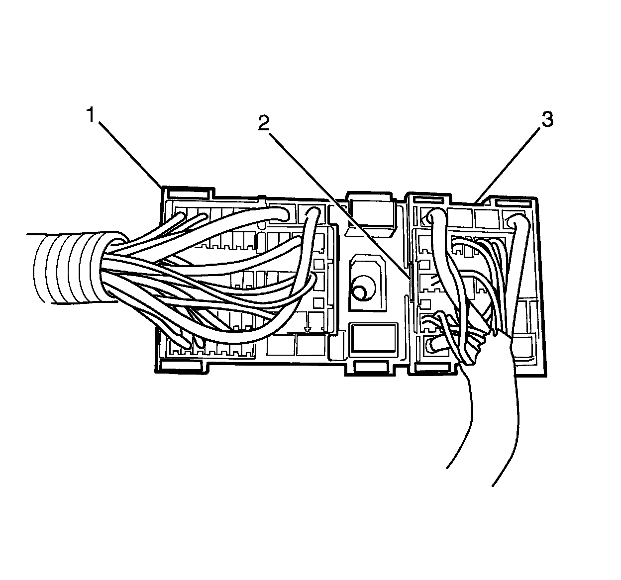
Listen for a audible click to confirm the correct installation of the engine connector (3).
98. Install the engine connector (3) into the body harness connector (1).
99. Install the protector (1) to the base of the under hood connector (2).
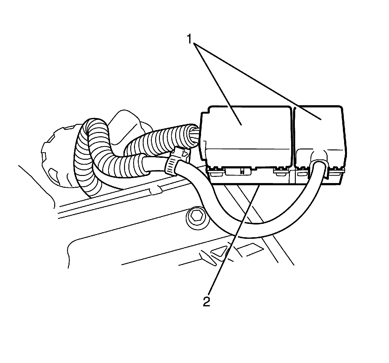
100. Install the upper under hood plate (1) to the lower under hood plate (3).
Note:
The under hood upper plate to lower plate retaining bolts (2) DO NOT have a torque specification. Listen for an audible clicking sound whilst tightening the under hood upper plate to lower plate retaining bolts (2) to confirm correct fitting.
101. Install the under hood upper plate to lower plate retaining bolts (2).
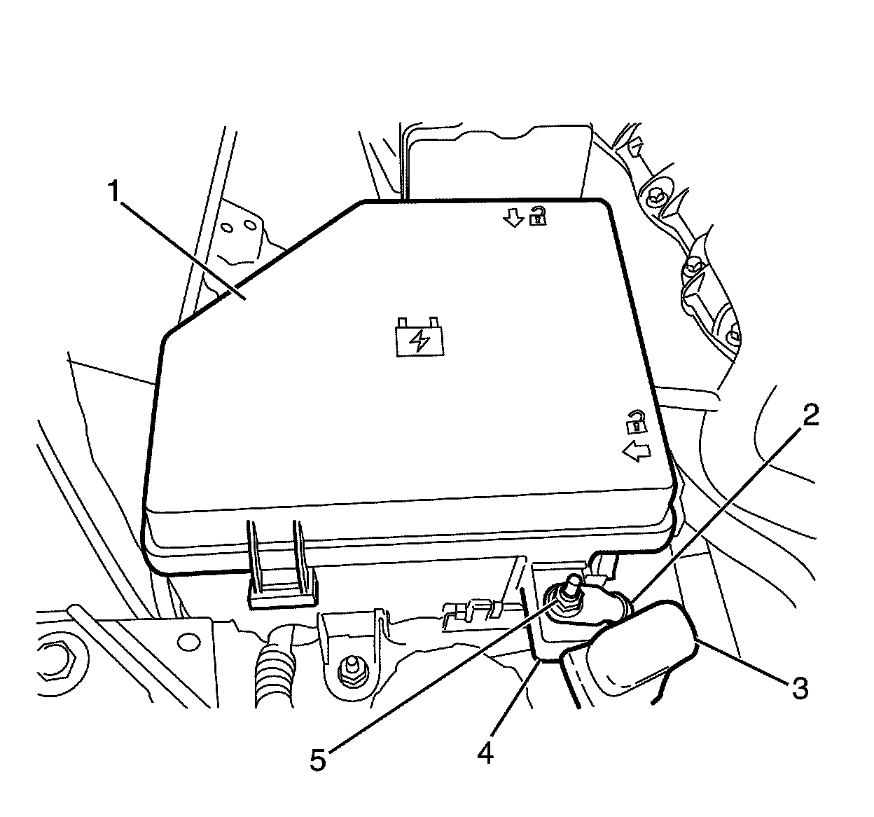
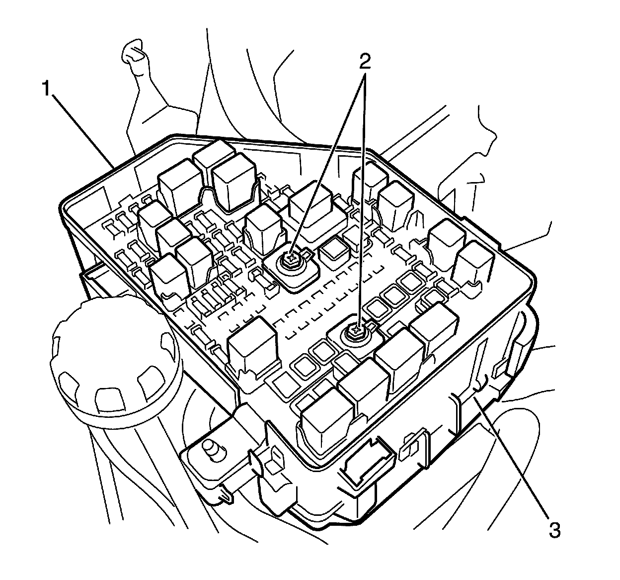
102. Connect the positive cable (2) to the upper under hood plate (4).
103. Install the positive cable to under hood plate retaining nut (5) and tighten to 10 Nm (89 lb in).
104. Install the under hood body electrical centre lid (1).
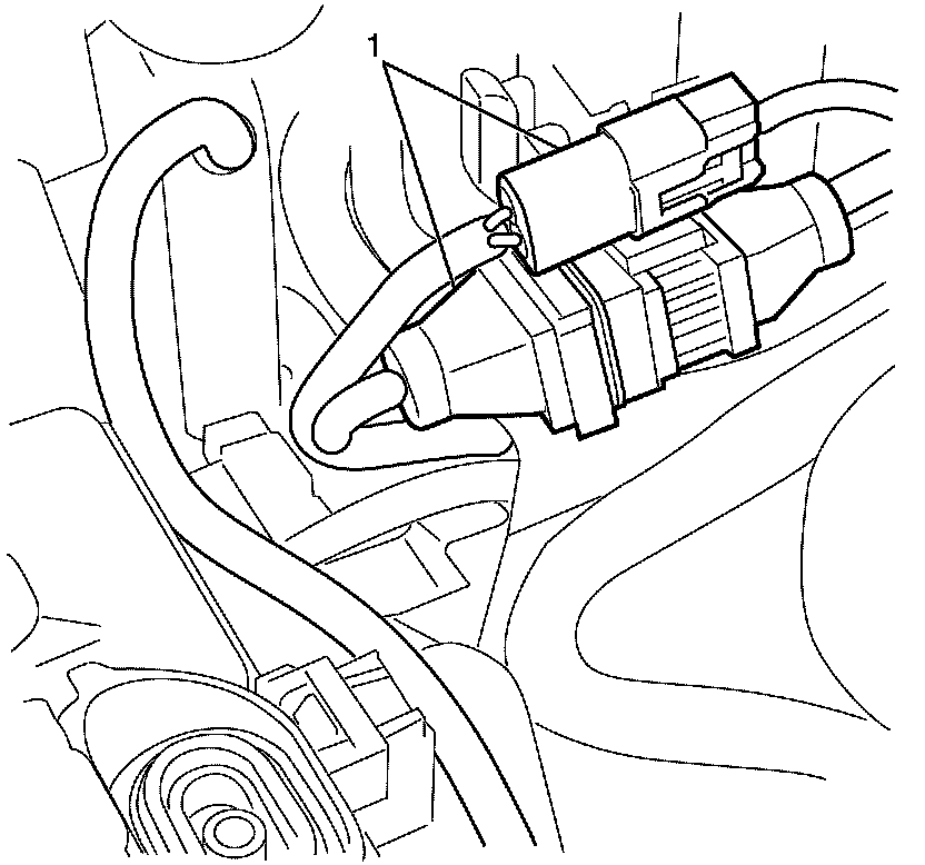
105. Connect the engine wiring harness connector (1) to the main engine wiring harness.
106. Connect the engine control module connectors. Refer to Engine Control Module Replacement Service and Repair.
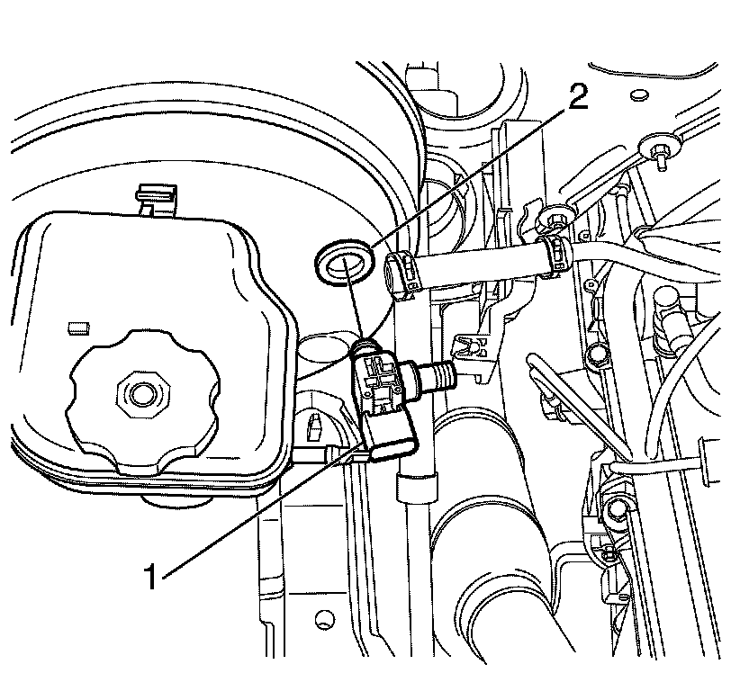
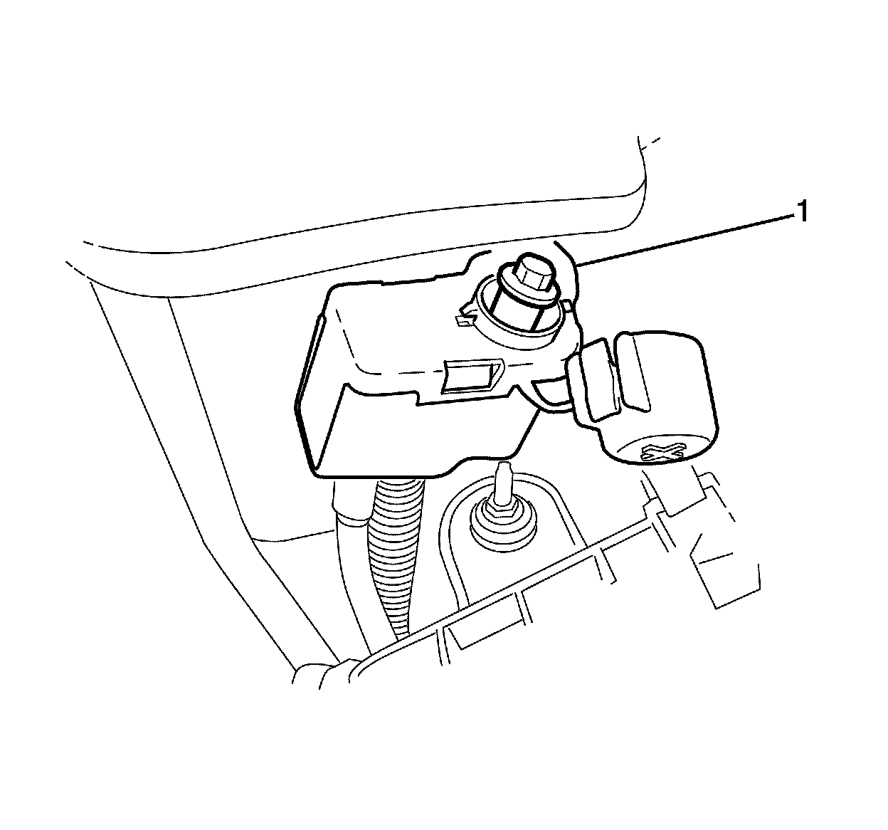
107. Install the brake booster vacuum pressure sensor/check valve (1) to the break booster.
108. Connect the engine wiring harness to the brake booster vacuum pressure sensor/check valve (1).
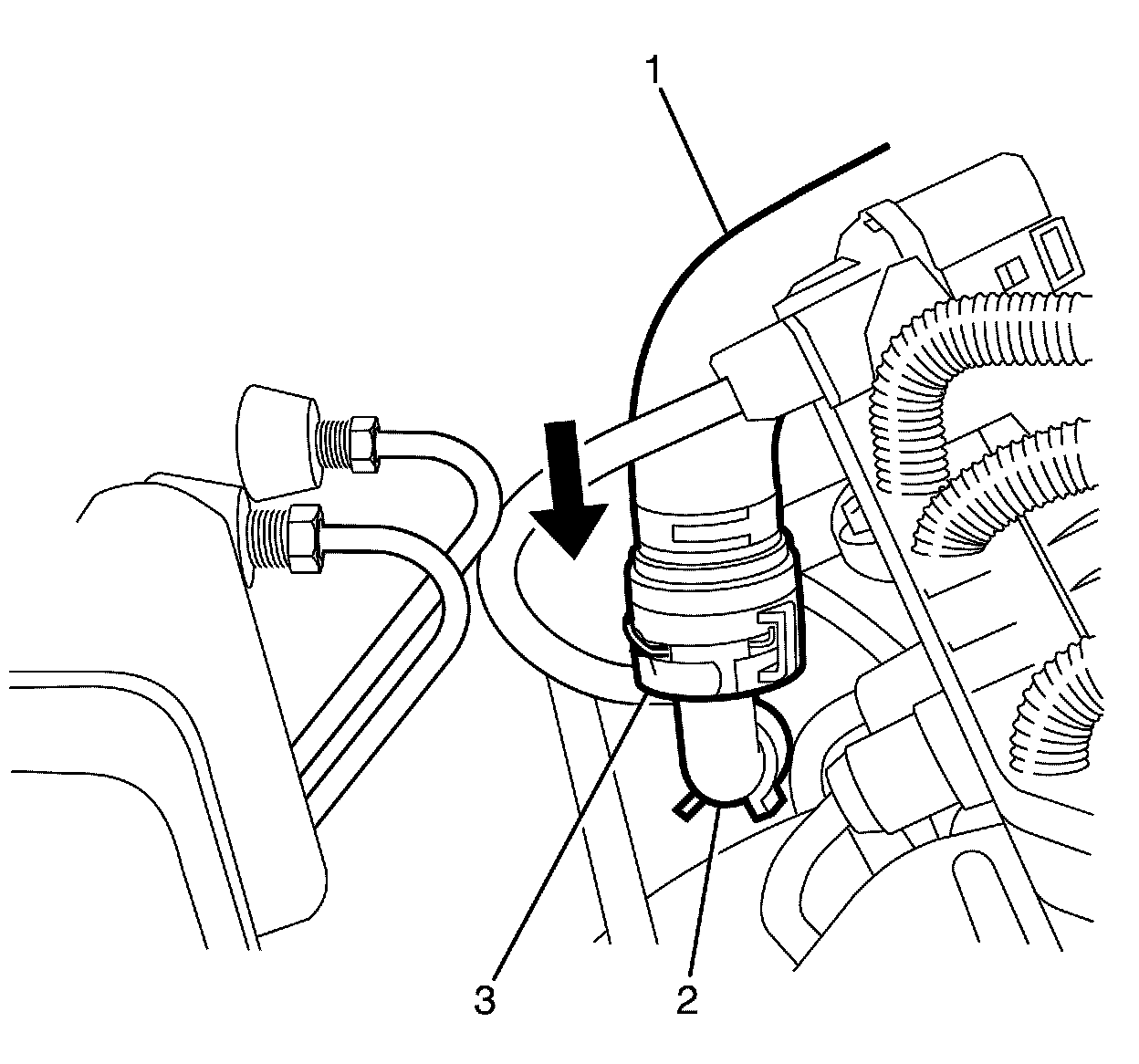
Note:
Listen for a audible click to confirm correct fitting of the heater hoses.
109. Install the heater hoses (1) to the heater pipe (2).

110. Remove the plug or cap from the ends of the cooling system hoses (3) and (2).
111. Install the coolant bleed hose (3) to the outlet housing (1).
112. Compress the coolant bleed hose retaining clamp (4) and position the coolant bleed hose retaining clamp (4) to its original position on the coolant bleed hose (3).
113. Install the coolant recovery hose (2) to the outlet housing (1).
114. Install the radiator outlet hose. Refer to Radiator Outlet Hose Replacement (LFX) Radiator Outlet Hose ReplacementRadiator Outlet Hose Replacement (L77) Radiator Outlet Hose Replacement.
115. Connect the battery ground cable. Refer to Battery Negative Cable Disconnection and Connection (Primary) Battery Negative Cable Disconnection and Connection (Primary)Battery Negative Cable Disconnection and Connection (Auxiliary) Battery Negative Cable Disconnection and Connection (Auxiliary).
116. Fill the cooling system. Refer to Cooling System Draining and Filling Cooling System Draining and Filling.
117. Install the air cleaner outlet duct. Refer to Air Cleaner Outlet Duct Replacement Air Cleaner Outlet Duct Replacement.
Note:
The A/C receiver and dehydrator are single use components.
118. Replace the A/C receiver and dehydrator. Refer to Receiver and Dehydrator Replacement Service and Repair.
119. Evacuate and recharge the A/C system. Refer to Refrigerant Recovery and Recharging Refrigerant Recovery and Recharging.
120. Install the air inlet grille. Refer to Air Inlet Grille Panel Replacement (Lower Panel) Air Inlet Grille Panel Replacement (Lower Panel)Air Inlet Grille Panel Replacement (Upper Panel) Air Inlet Grille Panel Replacement (Upper Panel).
121. Disable the ignition system with the scan tool.
122. Crank the engine several times and listen for any unusual noises.
123. Enable the ignition system.
124. Start the engine and listen for unusual noises.
125. Check the engine oil pressure and confirm that the engine oil pressure is acceptable.
126. Run the engine at about 1,000 RPM until the engine has reached normal operating temperature.
127. Listen for sticking stationary hydraulic lash adjuster, (SHLAs) (valve lifters) and other unusual noises.
Note:
When adding or changing transmission fluid use only recommend automatic transmission fluid.
128. Check the transmission fluid level and top up if required.
129. Inspect for fuel, oil, and/or other coolant leaks while the engine is running.
130. Leak test the A/C system using the J 39400-A.