Air Temperature Sensor ( Ambient / Intake ): Description and Operation
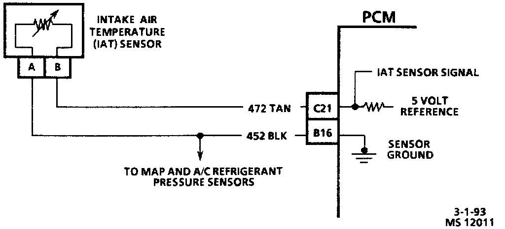
Intake Air Temperature (IAT) Sensor Circuit Diagram:
Mass Air Flow (MAF) & Intake Air Temperature (IAT) Sensor Locations:

DESCRIPTION
The intake air temperature sensor, installed in the intake air duct just behind the mass air flow sensor, is a thermistor with a negative temperature coefficient. Resistance through the sensor changes inversely with changes in temperature. Resistance is high when the sensor is cold, and decreases as temperature increases.
PURPOSE
Cold air is more dense than warm air and requires more fuel to maintain the same air/fuel ratio for a given volume of air. Also, gasoline does not atomize well in cold air, requiring still more fuel to maintain good driveability. The PCM uses intake air temperature as a factor in calculating the base injector pulse width for the required air/fuel ratio at different temperatures.
OPERATION
The PCM applies a 5 volt reference voltage to the sensor through a resistor in the PCM, and then monitors the voltage in the circuit. When the intake air is cold, resistance through the sensor will be high and the voltage in the circuit will be near the reference voltage of 5V. When the temperature increases, resistance drops, more current flows through the circuit and the voltage in the circuit will drop. Each voltage value corresponds to a specific resistance through the sensor and a specific air temperature. The PCM measures this voltage and calculates the temperature of the incoming air.