Oxygen Sensor O2S Heater Before Three Way Catalytic Converter, Checking
Oxygen Sensor O2S Heater Before Three Way Catalytic Converter, Checking
Observe all safety precautions: => [ Safety Precautions ] Safety Precautions
View clean working conditions: => [ Clean Working Conditions ] Clean Working Conditions
For wiring diagrams, component locations, and connector views, Refer to the applicable wiring diagram.
• Use only gold-plated terminals when servicing terminals in the electrical harness connector of the Heated Oxygen Sensor (HO2S) (G39) and Oxygen Sensor (O2S) Heater (Z19).
Special tools, testers and auxiliary items required
• Multimeter.
• Wiring diagram.
Test requirements
• The Oxygen Sensor (O2S) Heater (Z19) fuse OK.
• The Heated Oxygen Sensor (HO2S) (G39) before catalytic converter OK. Refer to=> [ Heated Oxygen Sensor HO2S Before Three Way Catalytic Converter, Checking ] Heated Oxygen Sensor HO2S Before Three Way Catalytic Converter, Checking.
• Battery voltage at least 12.5 volts.
• All electrical consumers such as, lights and rear window defroster, switched off.
• A/C switched off.
• Ground (GND) connections between engine/transmission/chassis OK.
• Exhaust system between catalytic converter and cylinder head properly sealed.
• Coolant Temperature at least 80 °C.
Test procedure
- Perform a preliminary check to verify the customers complaint. Refer to => [ Preliminary Check ] Preliminary Check.
Start diagnosis
• For connector location, removal and installation procedures. Refer to the appropriate service manual.
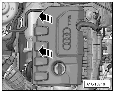
- Remove the engine cover. Refer to the appropriate service manual.
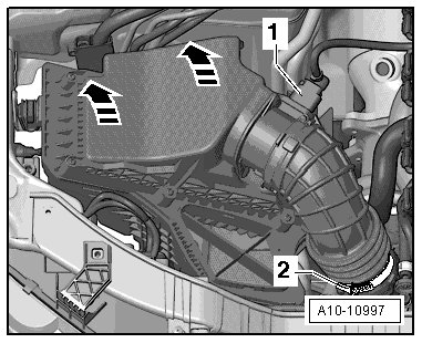
- Disconnect the connector -1- from the Mass airflow sensor (G70) , and remove the Air Filter Housing. Refer to appropriate service manual.
Checking primary voltage
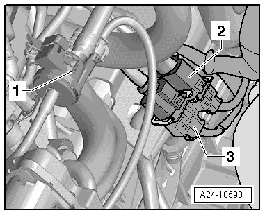
- Disconnect the Oxygen Sensor (O2S) Heater (Z19) electrical harness connector - 3 -.
Checking internal resistance
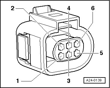
- Using a Multimeter, check the Oxygen Sensor (O2S) Heater (Z19) terminals 3 to 4 for resistance.
Specified value: 2.5 to 10.0 ohms (at approx. 20° C)
If the specified value was Not obtained:
- Replace the Oxygen Sensor (O2S) Heater (Z19). Refer to the appropriate service manual.
- Go to Final procedures
If the specified value was obtained:
Checking voltage supply
- Switch the ignition ON.
- Using a Multimeter, check the Heated Oxygen Sensor (HO2S) (G39) electrical harness connector terminal 4 to Ground (GND) for voltage.

- Switch the ignition OFF.
Specified value: Battery voltage.
If the specified value was Not obtained:
- Check the Oxygen sensor heater (Z19) electrical harness connector T6ab terminal 4 to Fuse SB 10 in Fuse Panel B Connector or an open circuit, a short circuit to each other or Ground (GND).
- Check the electrical harness connector for damage, corrosion, loose or broken terminals.
- If necessary, repair the faulty wiring connection.
- Repair the circuit and replace any open fuses.
- Go to Final procedures
If the specified value was obtained:
Checking Ground (GND) activation
- Remove the Engine Control Module (ECM) (J623). Refer to the appropriate service manual.
- Using a Multimeter, check the Heated Oxygen Sensor (HO2S) (G39) electrical harness connector terminal 3 to the Engine Control Module (ECM) (J623) electrical harness connector T94 for resistance.

Specified value: 1.5 ohms max.
If the specified value was Not obtained:
- Check the wiring for a short circuit to each other, Battery voltage, and Ground (GND).
- Check the electrical harness connector for damage, corrosion, loose or broken terminals.
- If necessary, repair the faulty wiring connection.
- Go to Final procedures
If the specified value was obtained:
- Replace the Engine Control Module (ECM) (J623). Refer to the appropriate service manual.
Final procedures
- Reinstall the engine covers, and Air Filter Housing, if necessary. Refer to the appropriate service manual.
- For connector location, removal and installation procedures. Refer to the appropriate service manual.
- After the repair work, the following work steps must be performed in the following sequence:
1. Check the DTC memory. Refer to => [ Diagnostic Mode 03 - Read DTC Memory ] Diagnostic Modes 01 - 0A.
2. If necessary, erase the DTC memory. Refer to => [ Diagnostic Mode 04 - Erase DTC Memory ] Diagnostic Modes 01 - 0A.
3. If the DTC memory was erased, generate readiness code. Refer to => [ Readiness Code ] Programming and Relearning