How to Proceed With Troubleshooting
CAN COMMUNICATION: CAN COMMUNICATION SYSTEM: HOW TO PROCEED WITH TROUBLESHOOTING
NOTICE:
* DTCs for the CAN communication system are as follows: U0073, U0100, U0105, U0121, U0129 and B1499.
* Refer to the troubleshooting section for each system if DTCs regarding the CAN communication system are not output.
* Turn the ignition switch off before measuring the resistances of the CAN main wire and the CAN branch wire.
* After the ignition switch is turned off, check that the key reminder warning system and light reminder warning system are not in operation.
* Before measuring the resistance, leave the vehicle for at least 1 minute and do not operate the ignition switch, any switches or doors. If doors need to be opened in order to check connectors, open the doors and leave them open.
HINT
Operating the ignition switch, any switches or any doors triggers related ECU and sensor communication with the CAN, which causes resistance variation.
1. CHECK AND CLEAR DTCs
NEXT -- Continue to next step.
2. CHECK INSTALLED SYSTEMS (ECUs AND SENSORS) THAT ADOPT CAN COMMUNICATION
NEXT -- Continue to next step.
3. CHECK CAN BUS LINE
(a) Check CAN bus line CAN Bus Line.
NEXT -- Continue to next step.
4. CHECK CAN COMMUNICATION USING INTELLIGENT TESTER VIA CAN VIM
(a) Select "BUS CHECK" Diagnosis System.
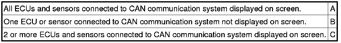
Result
NOTICE:
* The systems (ECUs and sensors) that adopt CAN communication vary depending on the vehicle and option settings. Check which systems (ECUs and sensors) are installed on the vehicle Diagnosis System.
* Non-installed ECUs or sensors are not displayed. Do not mistake them for being in communication stop mode.
* If 2 or more ECUs or sensors are not displayed on the intelligent tester via the CAN VIM, perform troubleshooting for open in one side of can bus line for each undisplayed ECU or sensor.
B -- GO TO COMMUNICATION STOP MODE TABLE
C -- GO TO OPEN IN ONE SIDE OF CAN BRANCH WIRE
A -- Continue to next step.
5. DTC COMBINATION TABLE
(a) Confirm trouble according to the combination of output DTCs regarding the CAN communication system.
HINT
Previous CAN communication system DTCs may be the cause if CAN communication system DTCs are output and all ECUs and sensors connected to the CAN communication system are displayed on the intelligent tester's "BUS CHECK" screen via CAN VIM.
NEXT -- Continue to next step.
6. INSPECT CIRCUIT
NEXT -- Continue to next step.
7. IDENTIFY PROBLEM
NEXT -- Continue to next step.
8. REPAIR OR REPLACE
NEXT -- Continue to next step.
9. PERFORM CONFIRMATION TEST
NEXT -- END