Pinpoint Test T: Intermittent No High Speed Controller Area Network (HS-CAN) Communication, One Or More Modules Are Not Respond
Communications Network
Pinpoint Tests
Pinpoint Test T: Intermittent No High Speed Controller Area Network (HS-CAN) Communication, One Or More Modules Are Not Responding During Network Test
Refer to Wiring Diagram Set 14, Module Communications Network for schematic and connector information. Diagrams By Number
Normal Operation
An open circuit (HS-CAN + or HS-CAN -) may cause intermittent or unreliable communication to all modules on the HS-CAN. The HS-CAN is used for communication between the following modules:
- 4X4 control module (if equipped)
- ABS module
- Accessory Protocol Interface Module (APIM) (if equipped)
- Instrument Cluster (IC)
- Occupant Classification System Module (OCSM)
- PCM
- Restraints Control Module (RCM)
- Transmission Control Module (TCM) (6R60 transmission only)
In the event that one of the 2 network circuits (HS-CAN + or HS-CAN -) becomes open to a module on the network, unreliable network communication to all modules on the network may result.
This pinpoint test is intended to diagnose the following:
- Wiring, terminals or connectors
- Data Link Connector (DLC)
PINPOINT TEST T: INTERMITTENT NO HS-CAN COMMUNICATION, ONE OR MORE MODULES ARE NOT RESPONDING DURING NETWORK TEST
NOTE: Various modules will set network DTCs during this test procedure. Clear DTCs from all modules after the diagnostic procedure is completed.
NOTE: Failure to disconnect the battery when instructed will result in false resistance readings. Refer to Battery.
-------------------------------------------------
T1 CHECK THE DLC PINS FOR DAMAGE
- Ignition OFF.
- Disconnect the scan tool cable from the DLC.
- Inspect DLC pins 6 and 14 for damage.
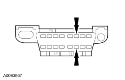
- Are DLC pins 6 and 14 OK?
Yes
GO to T2.
No
REPAIR the DLC as necessary. CLEAR the DTCs. REPEAT the network test with the scan tool.
-------------------------------------------------
T2 CHECK THE HS-CAN TERMINATION RESISTANCE
- Disconnect: Negative Battery Cable.
- Measure the resistance between the DLC C251-6, circuit VDB04 (WH/BU), harness side and the DLC C251-14, circuit VDB05 (WH), harness side.
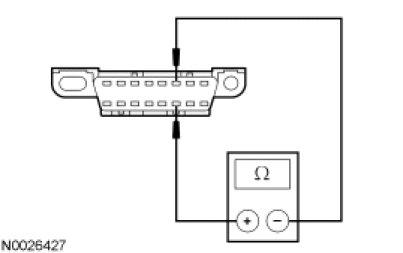
- Is the resistance between 54 and 66 ohms?
Yes
GO to T3.
No
CONNECT the negative battery cable. GO to Pinpoint Test U. Pinpoint Test U: No High Speed Controller Area Network (HS-CAN) Communication, All Modules Are Not Responding
-------------------------------------------------
T3 CHECK THE HS-CAN (+) AND HS-CAN (-) CIRCUITS FOR A SHORT TO GROUND
- Measure the resistance between the DLC C251-6, circuit VDB04 (WH/BU), harness side and ground; and between the DLC C251-14, circuit VDB05 (WH), harness side and ground.

- Are the resistances greater than 1,000 ohms?
Yes
CONNECT the negative battery cable. GO to T4.
No
CONNECT the negative battery cable. GO to Pinpoint Test U. Pinpoint Test U: No High Speed Controller Area Network (HS-CAN) Communication, All Modules Are Not Responding
-------------------------------------------------
T4 CHECK THE HS-CAN (+) AND HS-CAN (-) CIRCUITS FOR A SHORT TO VOLTAGE
- Ignition ON.
- Measure the voltage between the DLC C251-6, circuit VDB04 (WH/BU), harness side and ground; and between the DLC C251-14, circuit VDB05 (WH), harness side and ground.
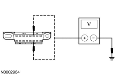
- Are the voltages greater than 6 volts?
Yes
REPAIR the circuit in question. CLEAR the DTCs. REPEAT the network test with the scan tool.
No
GO to T5.
-------------------------------------------------
T5 CHECK FOR RESTORED COMMUNICATION WITH THE PCM DISABLED
NOTE: A scan tool session must be established prior to disabling the PCM in this test step. If the PCM has failed communication during multiple attempts to identify the vehicle, first identify the vehicle manually by entering a PCM part number, calibration number or tear tag when prompted by the IDS.
NOTE: When a vehicle is manually identified by a PCM part number, calibration number or tear tag, the IDS will not automatically run a network test. The network test must be manually selected and run.
- Disconnect: BJB Fuse 24 (10A) and 39 (15A).
- Enter the following diagnostic mode on the scan tool: Network Test.
- Repeat the network test.
- Do all other modules pass the network test?
Yes
INSTALL the removed fuses. GO to Pinpoint Test A. Pinpoint Test A: The PCM Does Not Respond To The Scan Tool
No
INSTALL the removed fuses. GO to T6.
-------------------------------------------------
T6 CHECK FOR RESTORED NETWORK COMMUNICATION WITH THE ABS MODULE AND 4X4 CONTROL MODULE (IF EQUIPPED) DISABLED
NOTE: When re-running the network test, the network test application must first be closed or the screen display reverts back to the prior run network test results.
- Disconnect: SJB fuse 18 (10A).
- Enter the following diagnostic mode on the scan tool: Network Test.
- Repeat the network test.
- Do all other modules pass the network test?
Yes
INSTALL the removed fuse. If the vehicle is equipped with a 4X4 control module, GO to T7. If the vehicle is not equipped with a 4X4 control module, GO to Pinpoint Test C. Pinpoint Test C: The ABS Module Does Not Respond To The Scan Tool
No
INSTALL the removed fuse. GO to T8.
-------------------------------------------------
T7 CHECK FOR RESTORED NETWORK COMMUNICATION WITH THE ABS MODULE DISCONNECTED
NOTE: When re-running the network test, the network test application must first be closed or the screen display reverts back to the prior run network test results.
- Disconnect: ABS Module C155.
- Enter the following diagnostic mode on the scan tool: Network Test.
- Repeat the network test.
- Do all other modules pass the network test?
Yes
CONNECT the ABS module. GO to Pinpoint Test C. Pinpoint Test C: The ABS Module Does Not Respond To The Scan Tool
No
CONNECT the ABS module. GO to Pinpoint Test E. Pinpoint Test E: The 4X4 Control Module Does Not Respond To The Scan Tool
-------------------------------------------------
T8 CHECK FOR RESTORED NETWORK COMMUNICATION WITH THE RCM AND OCSM DISABLED
NOTE: When re-running the network test, the network test application must first be closed or the screen display reverts back to the prior run network test results.
- Disconnect: SJB Fuse 17 (10A).
- Enter the following diagnostic mode on the scan tool: Network Test.
- Repeat the network test.
- Do all other modules pass the network test?
Yes
INSTALL the removed fuse. GO to T9.
No
INSTALL the removed fuse. GO to T10.
-------------------------------------------------
T9 CHECK FOR RESTORED NETWORK COMMUNICATION WITH THE RCM DISCONNECTED
NOTE: When re-running the network test, the network test application must first be closed or the screen display reverts back to the prior run network test results.
- Disconnect: RCM C310b.
- Enter the following diagnostic mode on the scan tool: Network Test.
- Repeat the network test.
- Do all other modules pass the network test?
Yes
CONNECT the RCM. GO to Pinpoint Test D. Pinpoint Test D: The Restraints Control Module (RCM) Does Not Respond To The Scan Tool
No
CONNECT the RCM. GO to Pinpoint Test F. Pinpoint Test F: The Occupant Classification System Module (OCSM) Does Not Respond To The Scan Tool
-------------------------------------------------
T10 VERIFY VEHICLE EQUIPMENT - TCM
- A TCM is present in 6R60 transmission-equipped vehicles only. Inspect the vehicle for a 6R60 transmission.
- Is the vehicle equipped with a 6R60 transmission?
Yes
GO to T11.
No
GO to T12.
-------------------------------------------------
T11 CHECK FOR RESTORED NETWORK COMMUNICATION WITH THE TCM DISABLED
NOTE: When re-running the network test, the network test application must first be closed or the screen display reverts back to the prior run network test results.
- Disconnect: BJB Fuse 27 (20A) and SJB Fuse 9 (2A).
- Enter the following diagnostic mode on the scan tool: Network Test.
- Repeat the network test.
- Do all other modules pass the network test?
Yes
INSTALL the removed fuses. GO to Pinpoint Test B. Pinpoint Test B: The Transmission Control Module (TCM) Does Not Respond To The Scan Tool
No
INSTALL the removed fuses. GO to T12.
-------------------------------------------------
T12 VERIFY VEHICLE EQUIPMENT - APIM
- Inspect the vehicle for an APIM.
- Is the vehicle equipped with an APIM?
Yes
GO to T13.
No
GO to T14.
-------------------------------------------------
T13 CHECK FOR RESTORED NETWORK COMMUNICATION WITH THE APIM DISABLED
NOTE: When re-running the network test, the network test application must first be closed or the screen display reverts back to the prior run network test results.
- Disconnect: BJB Fuse 41 (15A).
- Enter the following diagnostic mode on the scan tool: Network Test.
- Repeat the network test.
- Do all other modules pass the network test?
Yes
INSTALL the removed fuse. GO to Pinpoint Test Q. Pinpoint Test Q: The Accessory Protocol Interface Module (APIM) Does Not Respond To The Scan Tool
No
INSTALL the removed fuse. GO to T14.
-------------------------------------------------
T14 CHECK FOR RESTORED NETWORK COMMUNICATION WITH THE IC DISABLED
NOTE: When re-running the network test, the network test application must first be closed or the screen display reverts back to the prior run network test results.
- Disconnect: SJB Fuses 8 (15A) and 24 (10A).
- Enter the following diagnostic mode on the scan tool: Network Test.
- Repeat the network test.
- Do all other modules pass the network test?
Yes
INSTALL the removed fuses. GO to Pinpoint Test G. Pinpoint Test G: The IC Does Not Respond To The Scan Tool
No
INSTALL the removed fuses. An intermittent fault is not present. GO to Pinpoint Test U. Pinpoint Test U: No High Speed Controller Area Network (HS-CAN) Communication, All Modules Are Not Responding
-------------------------------------------------