Part 2
Removing and installing engine (Continued)
Removing engine
Notice
Engine/transmission unit lowered or inserted incorrectly
^ Risk of damage to engine/transmission unit
^ Cables and coolant hoses can be stretched and torn
-> Gradually lower or raise the engine using a jack.
-> Always check that all necessary cables were disconnected when lowering the engine/transmission unit.
-> Make sure that no cables or hoses are damaged when fitting the engine/transmission unit.
-> Get one or two more persons to help.
1. Get an elevating platform Master Gear unit elevating platform WE 1206 -1- ready for removing the engine/transmission unit.
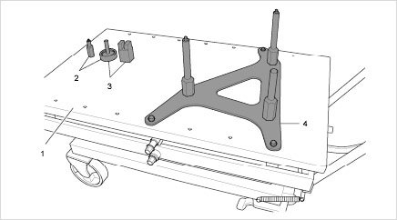
Master Gear unit elevating platform
1.1. Support 9769/1 -2- for vehicles with PDK transmission or support 9769/2 -3- for vehicles with manual transmission must be positioned in advance on the elevating platform.
1.2. Retainer plate 9769 -4- must be secured on the elevating platform with three screws.
2. Place elevating platform under engine/transmission unit.
2.1. Align retainer plate 9769 at the engine mounting points -arrows-. Make sure that the pins fit into the bores.
Engine mounting points
2.2. Fit the required transmission support -1- on the transmission.
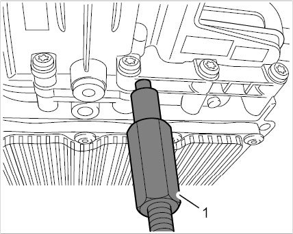
Tools support transmission (view 9769/1)
2.3. Slowly raise the elevating platform and support engine/transmission unit with a slight degree of pretension.
3. Loosen transmission mounts.
3.1. Loosen two hexagon nuts (a/f 13) -1- on each transmission mount and remove the screws.
Transmission mount screws
Transmission support in left direction of travel
3.2. Unscrew two M10 screws -1- on the left transmission support and remove the support as well as the transmission mounts.
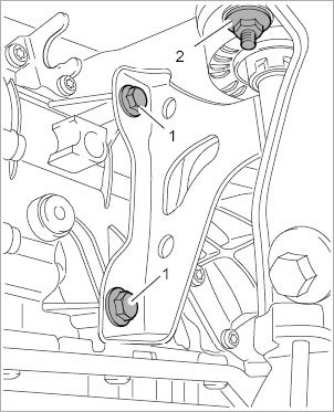
Transmission support in right direction of travel
3.3. Unscrew two M10 screws -1- on the right transmission support and remove the support as well as the transmission mounts.
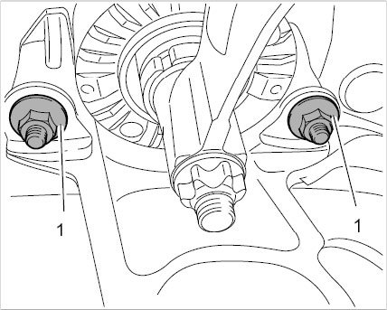
4. Unscrew four M10 hexagon collar nuts -arrows- on the engine carrier.
Engine carrier
5. Lower the engine/transmission unit slightly with the elevating platform.
6. Remove clutch slave cylinder.
7. Lower engine/transmission unit and guide the engine wire harness into the engine compartment.
7.1. A second person is required during the lowering process in order to prevent damage and collisions.
Installing engine
Notice
Engine/transmission unit lowered or inserted incorrectly
^ Risk of damage to engine/transmission unit
^ Cables and coolant hoses can be stretched and torn
-> Gradually lower or raise the engine using a jack.
-> Always check that all necessary cables were disconnected when lowering the engine/transmission unit.
-> Make sure that no cables or hoses are damaged when fitting the engine/transmission unit.
-> Get one or two more persons to help.
Information
^ The engine/transmission unit is installed in reverse order to removal. The following work steps are specifically repeated here in order to avoid damage.
Information
Always replace gaskets and O-rings.
^ Grease all gaskets (except for the cooling system) with Kluber Syntheso Glep (Part No. 000.043.204.68).
1. Fit the engine/transmission unit about halfway into the engine compartment and guide the engine wire harness through the assembly opening to the luggage compartment.
2. Vehicles with manual transmission: Install clutch slave cylinder.
3. Move engine/transmission unit into the final installation position.
4. Fit and tighten four M10 collar nuts -arrows- on the engine carrier. -> Tightening torque: 65 Nm (48 ftlb.).

Engine carrier
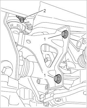
5. Install transmission support with hydraulic mount.
5.1. Secure transmission support on the transmission with two M10 hexagon-head bolts.
5.2. Fit two hexagon-head bolts and M8 hexagon nuts on each hydraulic mount.
5.3. Tighten collar nuts on the hydraulic mount and counter at the bolts.
-> Tightening torque: 23 Nm (17 ftlb.)
5.4. Tighten screws on the transmission support.
-> Tightening torque: 65 Nm (48 ftlb.)
6. Lower elevating platform and move out of work area. Remove special tool retainer plate 9592 from engine.
Subsequent work
Danger
Vehicle can fall down
^ Risk of squashing or crushing
^ Risk of damage to the vehicle
-> Do not place any solid objects under the raised vehicle.
-> Ensure that the lifting platform is prevented from lowering.
-> Remove solid objects before lowering the vehicle.
-> Raise the vehicle only at the take-up points provided.
Information
Always replace gaskets and O-rings.
^ Grease all gaskets (except for the cooling system) with Kluber Syntheso Glep (Part No. 000.043.204.68).
1. Attach coolant hoses and position spring band clamps.
Spring band clamps for coolant hoses
2. Fit large coolant hoses.
2.1. Fit coolant hoses into the Henn couplings. Ensure that the spring clamps are seated correctly -1-.
2.2. Clip in plastic holder -3-. Fit molded part -2-.
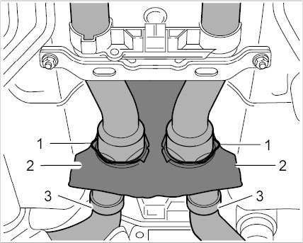
Coolant supply and return lines
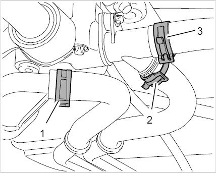
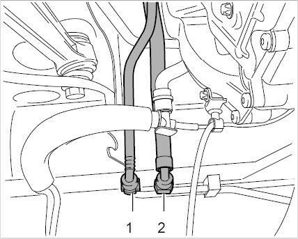
3. Connect fuel supply line -1- and tank vent line -2- to the underbody along with the lines for the fuel tank and carbon canister.
Fuel lines
Holder for hydraulic lines on the underbody
4. Join hydraulic lines for power-steering at the underbody and secure with holders.
5. Manual transmission: Engage shift and selector cables in the support and push onto ball pins.
Shift and selector cables, 6-speed
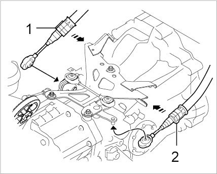
6. Porsche Double Clutch (PDK): Fit locking cable -1-.
Parking lock cable
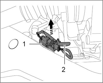
7. Connect vacuum line -1- with connecting piece -2- to the vacuum pump.
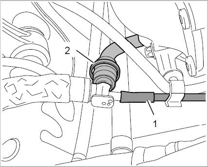
Vacuum connection for brake booster
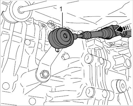
8. Fit drive shafts.
8.1. Fit and tighten six M10 hexagon socket head bolts on each.
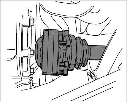
Drive shaft
9. Position ground strap -2- and tighten external Torx screw (M8 x 20) -1-.
-> Tightening torque: 23 Nm (17 ftlb.)
Engine ground strap
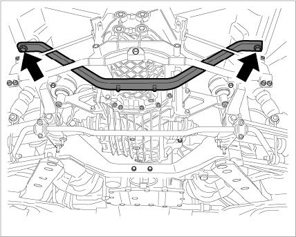
10. Install rear axle cross member.
11. Install exhaust manifold with catalytic converter.
12. Install exhaust system.
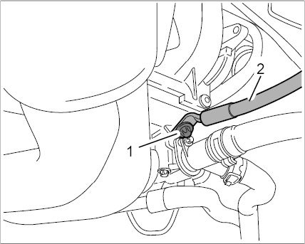
13. Connect and clip in connector -1- for oxygen sensors downstream of catalytic converter.
Connector for oxygen sensor downstream of catalytic converter
14. Fit oxygen sensors ahead of catalytic converter at the exhaust manifold.
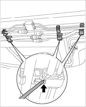
15. Guide restraining cable holder through the bores and tighten M8 nuts.
15.1. The cable must be countered with a suitable wrench and must not be twisted.
-> Tightening torque: 23 Nm (17 ftlb.)
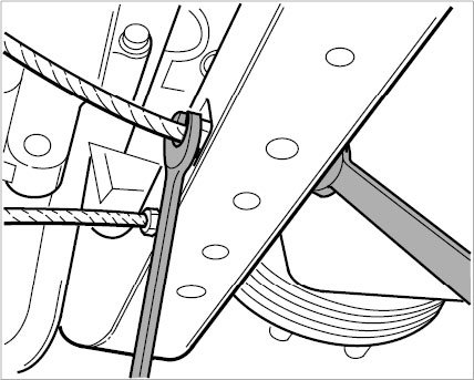
Restraining cable
16. Fit anti-roll bar.
16.1. Engage connecting link and fit M10 nuts -2-.
16.2. Fit and tighten hexagon-head bolts (M8 x 40) -1- on the anti-roll-bar mount.
-> Tightening torque: 23 Nm (17 ftlb.)
16.3. Tighten connecting link at the anti-roll bar - initial tightening.
-> Tightening torque, Stage 1: 50 Nm (37 ftlb.)
16.4. Loosen nuts by 90° and tighten to the prescribed torque - final tightening.
-> Tightening torque, Stage 2: 65 Nm (48 ftlb.)
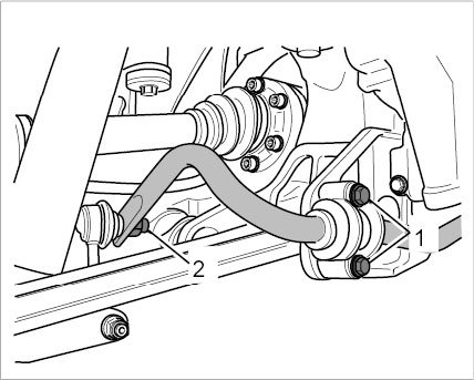
Anti-roll bar
17. Position V-strut and tighten hexagon-head bolts (M10 x 70) -arrows-. -> Tightening torque: 65 Nm (48 ftlb.).
V-strut
18. Install support plate -2- and diagonal braces -1-.
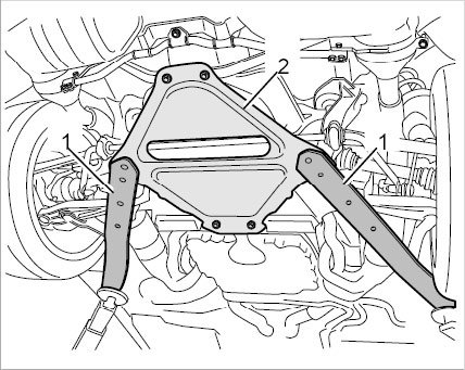
Support plate
19. Pull in rubber sleeve -1- for engine wire harness. Check that the rubber sleeve is seated correctly.
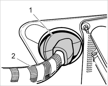
Fitting rubber sleeve
20. Plug in connectors for engine wire harness -1- and -2- above the left wheel arch.
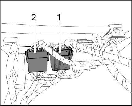
Connectors for engine wire harness
21. Position ground strap and tighten M6 nut -1-. -> Tightening torque: 10 Nm (7.5 ftlb.)
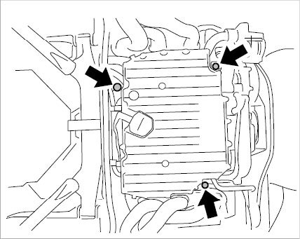
22. Plug in connectors at the engine control module.
Engine control unit
23. Vehicle with Porsche Double Clutch (PDK): Connect and lock two combination connectors on the transmission control unit.
24. Insert connectors for luggage compartment light.
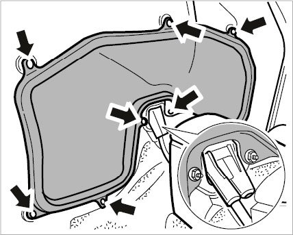
25. Fit rear luggage compartment trim.
25.1. Clip in fixing clips.
25.2. Fit luggage compartment lid seal.
26. Fit rubber sleeve between the mass air flow sensor and throttle housing.
26.1. Connect cable plug for mass air flow sensor.
27. Connect vent line for cooling system.
28. Plug in connector -1- for purge-air fan -2-.
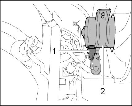
Connector on purge-air fan
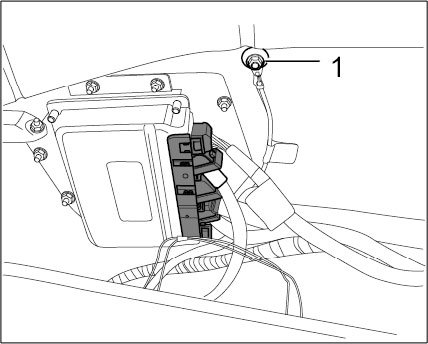
29. Fit B+ box for terminal 30 line in the engine compartment.
29.1. Tighten two hexagon nuts -1-.
-> Tightening torque: 10 Nm (7.5 ftlb.)
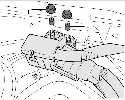
Junction point for terminal 30 line in engine compartment
30. Fit air-conditioning compressor lines at the underbody with new O-rings.
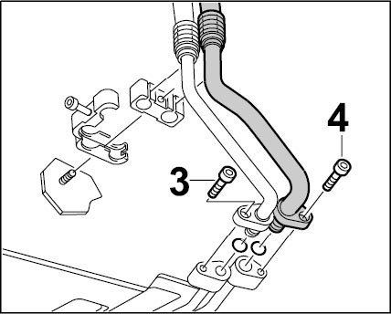
Installing line
31. Fill the air-conditioning system with refrigerant.
32. Fit both rear wheels.
32.1. Socket-wrench insert 300 should be used.
33. Connect battery ground strap.
34. Bleed and fill the cooling circuit.
35. Fill new hydraulic fluid (Pentosin) into the power-steering reservoir.
35.1. Start the engine. Turn the steering wheel from stop to stop while the engine is running in order to bleed the steering system.
36. Check all fluid levels and seal tightness after the engine test run.
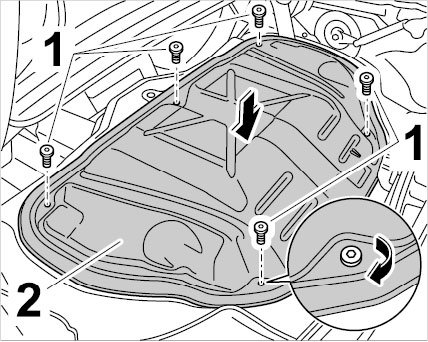
37. Install center underbody cover.
38. Install rear underbody cover.
39. Install rear wall cover.
Cover with grommet
40. Install engine compartment lid.
Engine compartment lid
41. Boxster: Close the hood.
42. Install linings (carpet for rear wall cover and engine cover).
43. Perform suspension alignment.
44. Read out fault memory and correct any faults that are present. Erase the fault memory.
45. Perform a test drive.