Exhaust Gas Recirculation (EGR) System Check
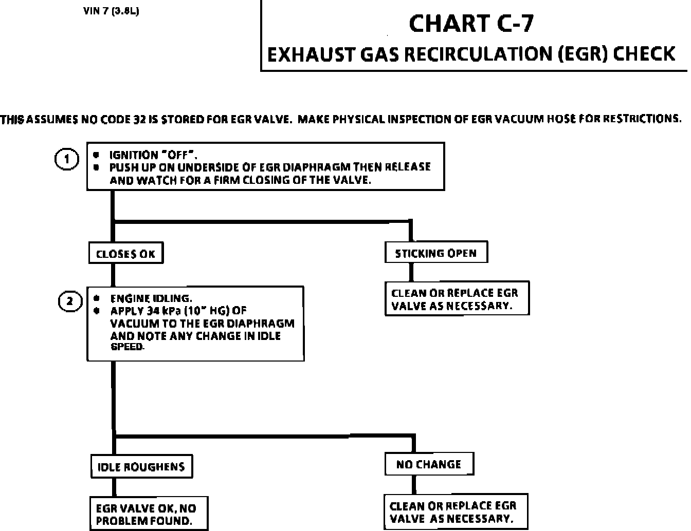
Chart C-7:
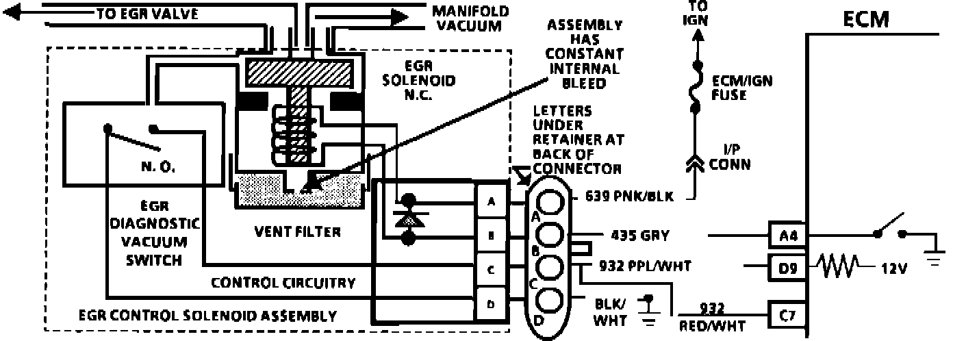
EGR Circuit Wiring Diagram:
EGR SYSTEM CHECK
CIRCUIT DESCRIPTION:
The EGR valve is operated by ported vacuum. This allows the exhaust gases to flow into the intake manifold. The exhaust gases then combines with the air/fuel mixture into the combustion chamber. If too much exhaust gas enters, combustion will not occur. For this reason, very little exhaust gas is allowed to pass through the valve, none at idle. The amount of EGR is controlled by variations in vacuum and the EGR control solenoid.
The EGR valve is usually open under the following conditions:
1. Warm engine operation
2. Throttle off-idle
TEST DESCRIPTION: The numbers below refer to circled numbers on the diagnostic chart.
1. This tests for a sticky EGR valve. If EGR valve is sticking, remove and inspect the valve to determine if it can be cleaned, or if it needs be replaced. A sticking EGR valve can cause a rough idle condition.
2. This checks for plugged EGR passages. If the passages are plugged, the engine may experiance severe detonation on acceleration, or under a heavy load.
NOTE: Once the test sequence is completed, clear codes and verify NO "SERVICE ENGINE SOON" light exists.
INCORRECT EGR OPERATION:
1. If too much EGR is flowing at idle, cruise, or cold operation,
any of the following conditions could exists:
a. The engine dies after cold start.
b. The engine stalls on deceleration.
c. The vehicle surges during cruise mode.
d. Rough idle.
2. If too little or no exhaust gases flow, the combustion chamber temperature may increase under acceleration or heavy load conditions. These conditions could cause:
a. Detonation (Spark Knock).
b. The engine to overheat.
c. The emissions test to fail.