Repair Procedures
Removal
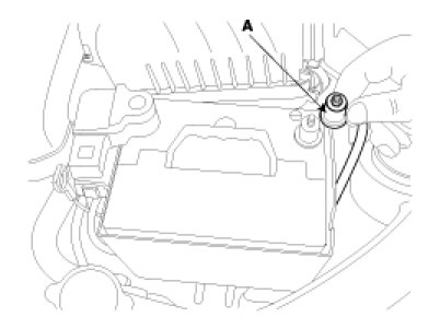
1. Disconnect the negative (-) terminal (A) from the battery.
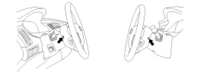
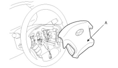
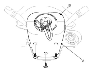
2. Loosen the bolts and lift up the horn pad and remove it.
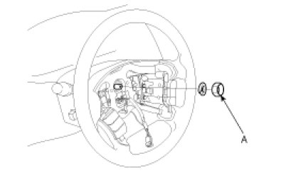
3. Remove the lock nut and the washer.
CAUTION:
Before doing these procedures, see the SRS section (RT Group. Only for vehicle equipped with SRS).
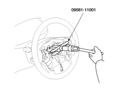
4. Remove the steering wheel with (09561-11001).
CAUTION:
Do not hammer on the steering wheel to remove it may cause the damage to the collapsible mechanism.
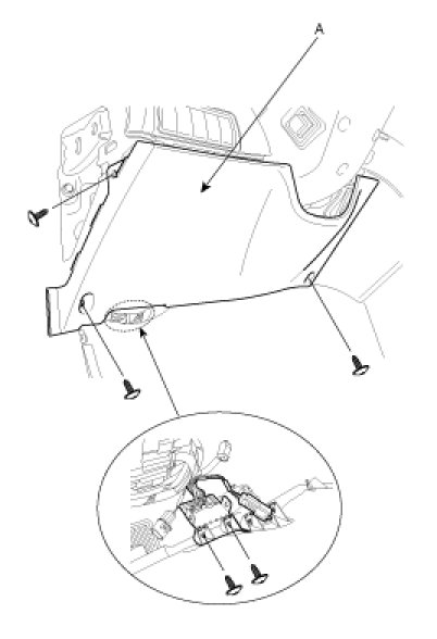
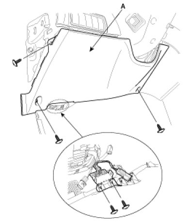
5. Remove the lower cover (A).
6. Remove the steering column lower (A) and upper shrouds (B).
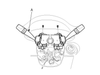
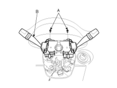
7. Disconnect the connectors and remove the multifunction switch (A).
8. Remove the bolt (A) securing the coupling and universal joint. Pull out the universal joint from the gear box.
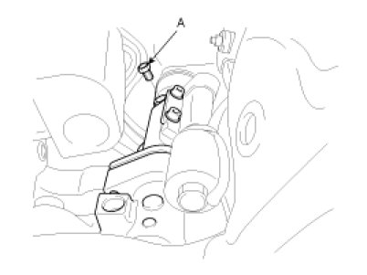
CAUTION:
Keep the neutral-range to prevent the damage of the clock spring inner cable when you handle the steering wheel.
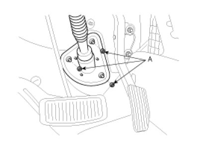
9. Remove the dust cover mounting nuts (A).
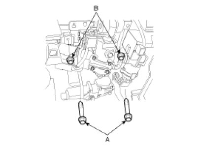
10. Remove the steering column mounting bolts (A) and nuts (B).
11. Remove the steering column and shaft with the universal joint and cover.
Disassembly
Key Lock Assembly
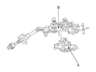
1. If it is necessary to remove the key lock assembly (A), use a punch to make a groove on the head of the special bolt (B), and then use a screwdriver to remove the key lock assembly mounting bracket (C).
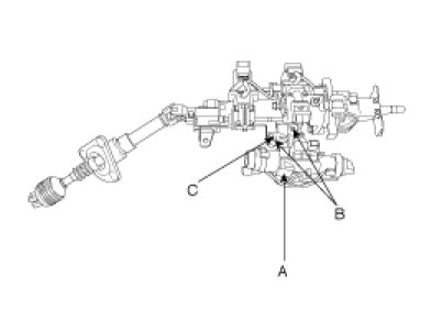
2. Disassemble the key lock assembly (A) from the steering column and shaft assembly (B).
3. Reassembly is reverse of disassembly.
Universal Joint Assembly
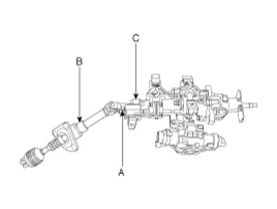
1. Remove the bolt (A) connecting the universal joint assembly (B) and the steering column and shaft assembly (C).
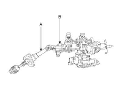
2. Remove the universal joint assembly (A) from the steering column and shaft assembly (B).
3. Reassembly is reverse of disassembly.
Inspection
1. Check the steering shaft for damage, play and round movement.
2. Check the upper and lower bearing for wear or damage.
3. Check the joints for excessive play, damage or rough movement.
4. Check the tilt bracket for cracks or damage.
5. Check the cover or boot for damage.
6. Check that the steering lock mechanism operates properly. If necessary, replace.
Reassembly
1. Reassembly is reverse of the removal.
2. Make parallel the steering shaft's groove to the hook of the steering lock, when installing the steering lock assembly.
Installation
1. Before installation, grease the inner side of the bearing, the boot, and the dust cover.
2. Install the steering column mounting bolts (A) and nuts (B).
Tightening torque :
13 - 18N.m (1.3 - 1.8kgf.m, 9.4 - 13lb-ft)
CAUTION:
Connect the universal joint to the pinion shaft of the gear box in advance
3. Install the dust cover mounting nuts (A).
Tightening torque :
13 - 18N.m (1.3 - 1.8kgf.m, 9.4 - 13lb-ft)
4. Install the connecting bolt (A) between the universal joint and the pinion shaft.
Tightening torque :
18 - 25N.m (1.8 - 2.5kgf.m, 13 - 18lb-ft)
5. Install the multifunction switch (B) mounting screws (A) and the connectors.
6. Install the steering column lower (A) and upper (B) shrouds.
CAUTION:
When installing the clock spring, set the center position by setting the marks between the clock spring and the cover into line. Make an array the mark (><) by turning the clock spring clockwise to the stop and then 2.0 revolutions counterclockwise.
7. Install the crush pad lower cover (A).
8. Install the steering wheel locking nut (A).
Tightening torque :
40 - 50N.m (4 - 5kgf.m, 28.9 - 36.1lb-ft)
NOTE:
Check that the front wheels is in the right direction in advance.
9. Install the horn pad (A) to steering wheel and tighten the bolts.
10. Connect the negative (-) terminal (A) to the battery.